SFI SYSTEM(w/o Canister Pump Module), Diagnostic DTC:P00CF62
| DTC Code | DTC Name |
|---|---|
| P00CF62 | Barometric Pressure - Turbocharger / Supercharger Boost Sensor "A" Signal Compare Failure |
DESCRIPTION
At engine switch on (IG) or during idling, the No. 2 turbo pressure sensor and the atmospheric pressure sensor built into the ECM are at atmospheric pressure and their outputs match.
| DTC No. | Detection Item | DTC Detection Condition | Trouble Area | MIL | Memory | Note |
|---|---|---|---|---|---|---|
| P00CF62 | Barometric Pressure - Turbocharger / Supercharger Boost Sensor "A" Signal Compare Failure | 15 kPa [2.18 psi] or greater difference between the atmospheric pressure values of the No. 2 turbo pressure sensor and the atmospheric pressure sensor (1 trip detection logic). |
|
Comes on | DTC stored | SAE: P00CF |
MONITOR DESCRIPTION
At engine switch on (IG) or during idling, the output values from the No. 2 turbo pressure sensor and the atmospheric pressure sensor built into the ECM are compared. If the difference in atmospheric pressure values is 15 kPa [2.18 psi] or greater, there may be a malfunction in the No. 2 turbo pressure sensor and atmospheric pressure sensor. In this case, the ECM illuminates the MIL and stores a DTC.
MONITOR STRATEGY
| Required Sensors/Components | No. 2 turbo pressure sensor Atmospheric pressure sensor |
| Frequency of Operation | Continuous |
CONFIRMATION DRIVING PATTERN
-
Connect the GTS to the DLC3.
-
Turn the engine switch is on (IG) and turn the GTS on.
-
Clear the DTCs (even if no DTCs are stored, perform the clear DTC procedure).
-
Turn the engine switch off and wait for at least 30 seconds.
-
Turn the engine switch is on (IG) and turn the GTS on.
-
Start the engine and wait 5 seconds or more.
-
Enter the following menus: Powertrain / Engine / Trouble Codes.
-
Read the pending DTCs.
Tech Tips
-
If a pending DTC is output, the system is malfunctioning.
-
If a pending DTC is not output, perform the following procedure.
-
-
Enter the following menus: Powertrain / Engine / Utility / All Readiness.
-
Input the DTC: P00CF62.
-
Check the DTC judgment result.
GTS Display Description NORMAL
-
DTC judgment completed
-
System normal
ABNORMAL
-
DTC judgment completed
-
System abnormal
INCOMPLETE
-
DTC judgment not completed
-
Perform driving pattern after confirming DTC enabling conditions
N/A
-
Unable to perform DTC judgment
-
Number of DTCs which do not fulfill DTC preconditions has reached ECU memory limit
Tech Tips
-
If the judgment result shows NORMAL, the system is normal.
-
If the judgment result shows ABNORMAL, the system has a malfunction.
-
CAUTION / NOTICE / HINT
Tech Tips
Read freeze frame data using the GTS. The ECM records vehicle and driving condition information as freeze frame data the moment a DTC is stored. When troubleshooting, freeze frame data can help determine if the vehicle was moving or stationary, if the engine was warmed up or not, if the air fuel ratio was lean or rich, and other data from the time the malfunction occurred.
PROCEDURE
-
CHECK ANY OTHER DTCS OUTPUT (IN ADDITION TO DTC P00CF62)
-
Connect the GTS to the DLC3.
-
Turn the engine switch on (IG).
-
Turn the GTS on.
-
Enter the following menus: Powertrain / Engine / Trouble Codes.
-
Read the DTCs.
Powertrain > Engine > Trouble CodesResult Result Proceed to DTC P00CF62 is output A DTC P00CF62 and P023400, P023562, P211900, P211904 or P211977 are output DTC P00CF62 and P023400, P023562, P211900, P211904 or P211977 and other DTCs are output B Tech Tips
If any DTCs other than P00CF62 and P023400, P023562, P211900, P211904 or P211977 are output, troubleshoot those DTCs first.
B 
GO TO DTC CHART Click here
A 
-
-
READ VALUE USING GTS (ATMOSPHERIC PRESSURE AND BOOST PRESSURE SENSOR)
-
Connect the GTS to the DLC3.
-
Turn the engine switch on (IG).
-
Turn the GTS on.
-
Enter the following menus: Powertrain / Engine / Data List / Atmospheric Pressure and Boost Pressure Sensor.
Powertrain > Engine > Data ListTester Display Atmospheric Pressure Boost Pressure Sensor -
Compare Atmospheric Pressure and Boost Pressure Sensor in the Data List.
Result Result Proceed to Difference between Atmospheric Pressure and Boost Pressure Sensor in the Data List exceeds 13 kPa [1.89 psi] A Other than above B
B 
CHECK INTAKE SYSTEM Click here
A
-
-
READ VALUE USING GTS (ATMOSPHERIC PRESSURE AND BOOST PRESSURE SENSOR)
-
Connect the GTS to the DLC3.
-
Turn the engine switch on (IG).
-
Enter the following menus: Powertrain / Engine / Data List / Atmospheric Pressure and Boost Pressure Sensor.
Powertrain > Engine > Data ListTester Display Atmospheric Pressure Boost Pressure Sensor -
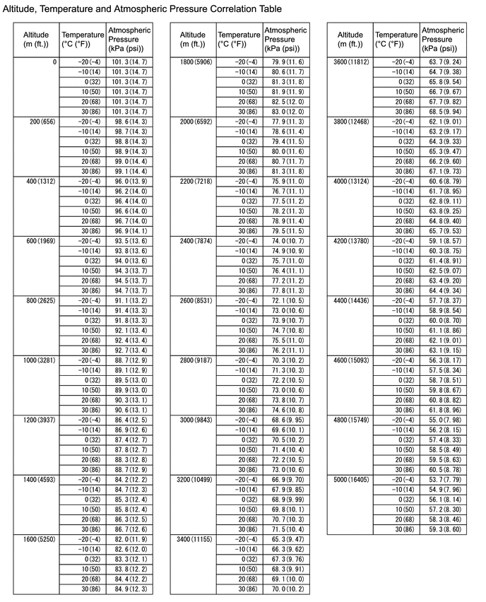
Using the table, read the normal atmospheric pressure value for the applicable altitude and temperature.
Tech Tips
-
Standard atmospheric pressure is approximately 101 kPa(abs) [14.65 psi(abs)].
-
For every 100 m (328 ft.) increase in altitude, atmospheric pressure drops by approximately 1 kPa [0.15 psi]. This varies by weather.
-
-
Compare the Atmospheric Pressure and Boost Pressure Sensor values in the Data List with the normal atmospheric value from the table.
Result Result Proceed to Difference between (difference between Boost Pressure Sensor in the Data List and normal atmospheric pressure) and (difference between Atmospheric Pressure in the Data List and normal atmospheric pressure) is 4 kPa [0.58 psi] or greater A Other than above B Tech Tips
-
As the table below shows reference values only, use actual values for calculations.
-
In Example 1, as the pressure difference is 4 kPa [0.58 psi] or higher, proceed to the next step.
-
In Example 2, as the pressure difference is less than 4 kPa [0.58 psi], replace the ECM.
Item Example 1 Example 2 Atmospheric pressure Difference to normal atmospheric pressure Difference between (difference between Boost Pressure Sensor in the Data List and normal atmospheric pressure) and (difference between Atmospheric Pressure in the Data List and normal atmospheric pressure) Atmospheric pressure Difference to normal atmospheric pressure Difference between (difference between Boost Pressure Sensor in the Data List and normal atmospheric pressure) and (difference between Atmospheric Pressure in the Data List and normal atmospheric pressure) Normal atmospheric pressure 100 kPa(abs) [15.5 psi(abs)] - 6 kPa [0.87 psi] 100 kPa(abs) [15.5 psi(abs)] - 2 kPa [0.29 psi] Boost Pressure Sensor in the Data List 110 kPa(abs) [15.95 psi(abs)] 10 kPa [1.45 psi] 108 kPa(abs) [15.66 psi(abs)] 8 kPa [1.16 psi] Atmospheric Pressure in the Data List 96 kPa(abs) [13.92 psi(abs)] 4 kPa [0.58 psi] 94 kPa(abs) [13.63 psi(abs)] 6 kPa [0.87 psi] -
B
REPLACE ECM Click here
A
-
-
CHECK TERMINAL VOLTAGE (POWER SOURCE OF NO. 2 TURBO PRESSURE SENSOR)
-
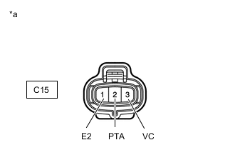
*a Front view of wire harness connector
(to No. 2 Turbo Pressure Sensor)
Disconnect the No. 2 turbo pressure sensor connector.
-
Turn the engine switch on (IG).
-
Measure the voltage according to the value(s) in the table below.
Standard Voltage Tester Connection Condition Specified Condition C15-3 (VC) - C15-1 (E2) Engine switch on (IG) 4.5 to 5.5 V C15-2 (PTA) - C15-1 (E2) Engine switch on (IG) 3.0 to 5.5 V Result Proceed to OK NG
NG
CHECK HARNESS AND CONNECTOR (NO. 2 TURBO PRESSURE SENSOR - ECM) Click here
OK
-
-
REPLACE NO. 2 TURBO PRESSURE SENSOR
-
Replace the No. 2 turbo pressure sensor.
Result Proceed to NEXT
NEXT
-
-
CHECK WHETHER DTC OUTPUT RECURS (DTC P00CF62)
-
Connect the GTS to the DLC3.
-
Turn the engine switch on (IG).
-
Turn the GTS on.
-
Clear the DTCs.
Powertrain > Engine > Clear DTCs -
Turn the engine switch off and wait for at least 30 seconds.
-
Start the engine.
-
Turn the GTS on.
-
Drive the vehicle in accordance with the driving pattern described in Confirmation Driving Pattern.
-
Enter the following menus: Powertrain / Engine / Utility / All Readiness.
Powertrain > Engine > UtilityTester Display All Readiness -
Input the DTC: P00CF62.
-
Check the DTC judgment result.
Result Result Proceed to NORMAL
(DTCs are not output)
A ABNORMAL
(DTC P00CF62 is output)
B
A
END
B
REPLACE ECM Click here
-
-
CHECK HARNESS AND CONNECTOR (NO. 2 TURBO PRESSURE SENSOR - ECM)
-
Disconnect the No. 2 turbo pressure sensor connector.
-
Disconnect the ECM connector.
-
Measure the resistance according to the value(s) in the table below.
Standard Resistance Tester Connection Condition Specified Condition C15-3 (VC) - C20-140 (VPTA) Always Below 1 Ω C15-1 (E2) - C20-139 (EPTA) Always Below 1 Ω C15-2 (PTA) - C20-108 (PTA) Always Below 1 Ω C15-3 (VC) or C20-140 (VPTA) - Body ground and other terminals Always 10 kΩ or higher C15-2 (PTA) or C20-108 (PTA) - Body ground and other terminals Always 10 kΩ or higher Result Proceed to OK NG
OK
REPLACE ECM Click here
NG
REPAIR OR REPLACE HARNESS OR CONNECTOR
-
-
CHECK INTAKE SYSTEM
-
Check that there is no air suction or blockage at any points in the intake system.
OK No air suction or blockage. Tech Tips
Perform "Inspection After Repair" after repairing or replacing the intake system.
Result Proceed to OK NG
OK
GO TO STEP 6 Click here
NG
REPAIR OR REPLACE INTAKE SYSTEM
-