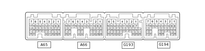
DYNAMIC RADAR CRUISE CONTROL SYSTEM TERMINALS OF ECU
CHECK HYBRID VEHICLE CONTROL ECU
Terminal No. (Symbol)
Wiring Color
Terminal Description
Condition
Specified Condition
A65-15 (STP) - G193-6 (E1)
L - BR
Stop light switch assembly signal
Brake pedal depressed
11 to 14 V
Brake pedal released
0 to 1.5 V
G193-28 (CCS) - G193-6 (E1)
SB - BR
Cruise control main switch circuit
Cruise control main switch (ON/OFF) off
1 MΩ or higher
Cruise control main switch (ON/OFF) on
Below 2.5 Ω
+/RES switch on
236 to 244 Ω
-/SET switch off
618 to 642 Ω
CANCEL switch on
1510 to 1570 Ω
A66-28 (ST1-) - G193-6 (E1)
GR - BR
Stop light signal
Power switch on (IG), Brake pedal depressed
0 to 1.5 V
Power switch on (IG), Brake pedal released
11 to 14 V
A66-14 (DB2) - G193-6 (E1)
Y - BR
Shift lever position signal
Power switch on (IG), shift lever in D or S
11 to 14 V
Power switch on (IG), shift lever not in D or S
0 to 1.5 V
A66-26 (DB1) - G193-6 (E1)
V - BR
Shift lever position signal
Power switch on (IG), shift lever in D or S
11 to 14 V
Power switch on (IG), shift lever not in D or S
0 to 1.5 V
G193-6 (E1) - Body ground
BR - Body ground
Ground
Always
Below 1 Ω
G194-1 (M) - G193-6 (E1)
L - BR
S shift position switch signal
Power switch on (IG), shift lever in S
11 to 14 V
Power switch on (IG), shift lever is not in S
0 to 1.5 V
G194-8 (SFTD) - G193-6 (E1)
SB - BR
Down shift switch signal
Power switch on (IG) and shift lever in S
11 to 14 V
Power switch on (IG) and shift lever "-" position (Down shift)
0 to 1.5 V
G194-9 (SFTU) - G193-6 (E1)
V - BR
Up shift switch signal
Power switch on (IG) and shift lever in S
11 to 14 V
Power switch on (IG) and shift lever "+" position (Up shift)
0 to 1.5 V
CHECK DRIVING SUPPORT ECU ASSEMBLY

Terminal No. (Symbol)
Wiring Color
Terminal Description
Condition
Specified Condition
G168-3 (BZ) - G168-28 (GND)
LG - BR
Skid control buzzer output
Power switch on (IG), Skid control buzzer not sounding
11 to 14 V
G168-7 (B) - G168-28 (GND)
B - BR
Power source
Power switch on (IG)
11 to 14 V
G168-8 (CA1P) - G168-28 (GND)
B - BR
CAN communication signal
Power switch on (IG)
Pulse generation
(See waveform 1)
G168-9 (CA1N) - G168-28 (GND)
W - BR
CAN communication signal
Power switch on (IG)
Pulse generation
(See waveform 2)
G168-10 (CA2H) - G168-28 (GND)
P - BR
CAN communication signal
Power switch on (IG)
Pulse generation
(See waveform 1)
G168-11 (CA2L) - G168-28 (GND)
LG - BR
CAN communication signal
Power switch on (IG)
Pulse generation
(See waveform 2)
G168-23 (SPSW) - G168-28 (GND)
B - BR
Steering pad switch signal (vehicle-to-vehicle distance control switch signal)
Power switch on (IG), Vehicle-to-vehicle distance control switch on
Below 1 Ω
G168-23 (SPSW) - G168-28 (GND)
B - BR
Steering pad switch signal (vehicle-to-vehicle distance control switch signal)
Power switch on (IG), Vehicle-to-vehicle distance control switch off
4.75 to 5.25 V
G168-28 (GND) - Body ground
BR - Body ground
Ground
Always
Below 1 Ω
-
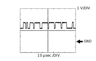
Waveform 1
CAN communication signal
Item
Content
Terminal Name
Between G168-8 (CA1P) and G168-28 (GND)
Between G168-10 (CA2H) and G168-28 (GND)
Tester Range
1 V/DIV., 10 μsec./DIV.
Condition
Power switch on (IG)
Tip:The waveform varies depending on the CAN communication signal.
-
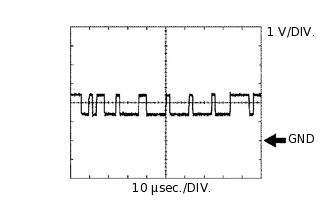
Waveform 2
CAN communication signal
Item
Content
Terminal Name
Between G168-9 (CA1N) and G168-28 (GND)
Between G168-11 (CA2L) and G168-28 (GND)
Tester Range
1 V/DIV., 10 μsec./DIV.
Condition
Power switch on (IG)
Tip:The waveform varies depending on the CAN communication signal.
-
CHECK MILLIMETER WAVE RADAR SENSOR

Terminal No. (Symbol)
Wiring Color
Terminal Description
Condition
Specified Condition
Z6-1 (SGND) - Body ground
BR - Body ground
Ground
Always
Below 1 Ω
Z6-2 (CA2L) - Z6-1 (SGND)
LG - BR
CAN communication signal
Power switch on (IG)
Pulse generation
(See waveform 2)
Z6-3 (CA2H) - Z6-1 (SGND)
B - BR
CAN communication signal
Power switch on (IG)
Pulse generation
(See waveform 1)
Z6-5 (CA1P) - Z6-1 (SGND)
SB - BR
CAN communication signal
Power switch on (IG)
Pulse generation
(See waveform 1)
Z6-6 (CA1N) - Z6-1 (SGND)
W - BR
CAN communication signal
Power switch on (IG)
Pulse generation
(See waveform 2)
Z6-8 (IGB) - Z6-1 (SGND)
L - BR
Power source
Power switch on (IG)
11 to 14 V
-
Waveform 1
CAN communication signal
Item
Content
Terminal Name
Between Z6-3 (CA2H) and Z6-1 (SGND)
Between Z6-5 (CA1P) and Z6-1 (SGND)
Tester Range
1 V/DIV., 10 μsec./DIV.
Condition
Power switch on (IG)
Tip:The waveform varies depending on the CAN communication signal.
-
Waveform 2
CAN communication signal
Item
Content
Terminal Name
Between Z6-2 (CA2L) and Z6-1 (SGND)
Between Z6-6 (CA1N) and Z6-1 (SGND)
Tester Range
1 V/DIV., 10 μsec./DIV.
Condition
Power switch on (IG)
Tip:The waveform varies depending on the CAN communication signal.
-