FRONT SIDE MEMBER CUT AND JOIN REPLACEMENT SECTIONS (SMALL AREAS)
-
With the radiator support and front fender mounting bracket removed.
-
REMOVAL
Symbol meaning 
Remove Weld Points 
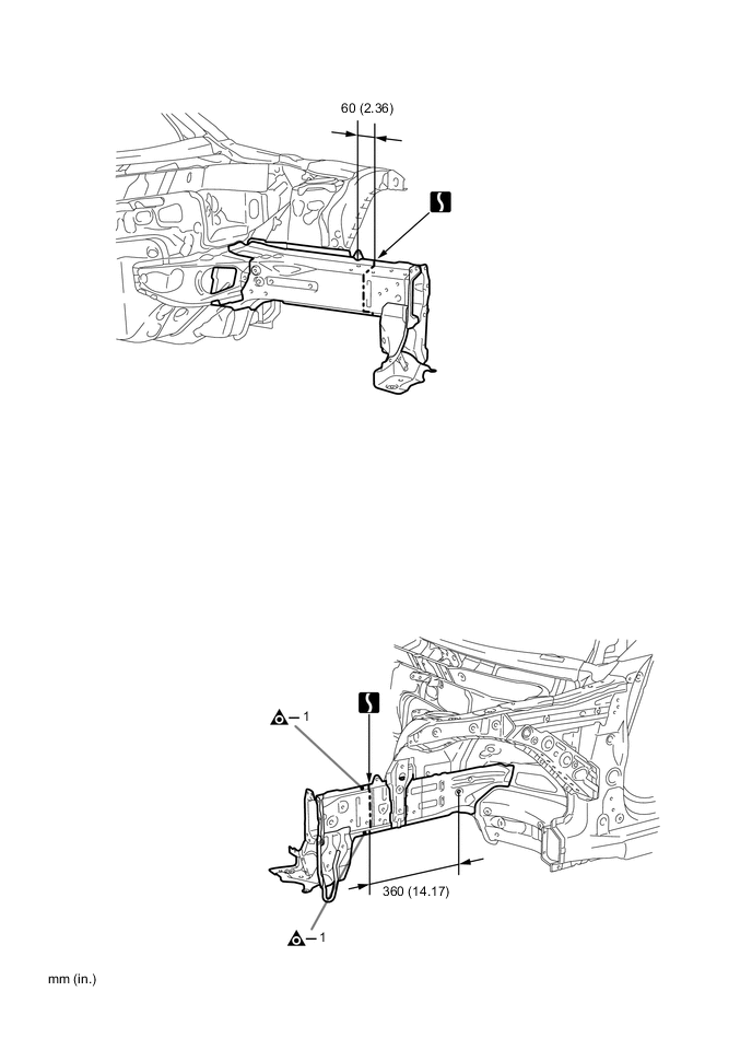
Cut and Join Location
-
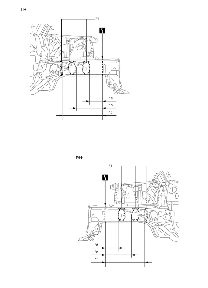
Carefully cut the member so not to damage *1.
Reference Value Area Measurement Area Measurement *a 135 mm (5.31 in.) *b 271 mm (10.67 in.) *c 410 mm (16.14 in.) *d 135 mm (5.31 in.) *e 271 mm (10.67 in.) *f 410 mm (16.14 in.)
REMOVAL POINT
-
-
INSTALLATION
Symbol meaning 
Plug Weld 
Butt Weld
-
Temporarily install the new parts and measure each part of the new parts in accordance with the body dimension diagram. (See the body dimensions)
-
After welding, apply body sealer and undercoating to the corresponding parts. (See the painting / coating)
-
After applying the top coat, apply anti-rust agent to the internal panel portion of the closed section structural weld points.
INSTALLATION POINT
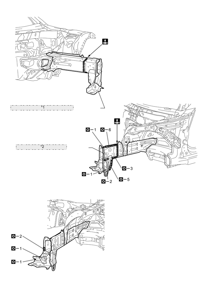
*1 FRONT SIDE MEMBER SUB-ASSEMBLY INNER *2 FRONT SIDE MEMBER PLATE OUTER -