INSTRUMENT PANEL SAFETY PAD INSTALLATION
PROCEDURE
-
INSTALL INSTRUMENT PANEL SAFETY PAD SUB-ASSEMBLY
-
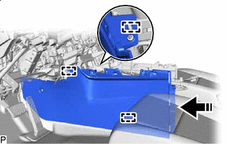
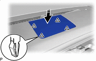
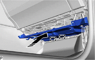
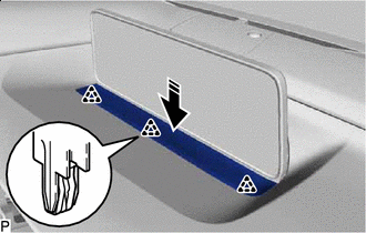
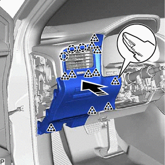
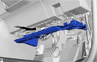
Engage the 4 guides to temporarily install the instrument panel safety pad sub-assembly as shown in the illustration.
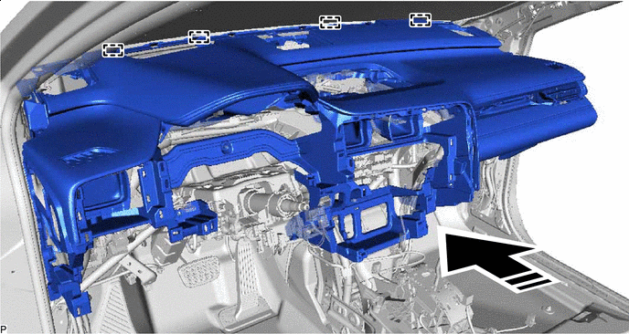

Install in this Direction - - Note
-
Do not damage the instrument panel safety pad sub-assembly.
-
Do not allow the wire harnesses to interfere with the surrounding parts.
-
-
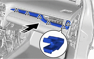
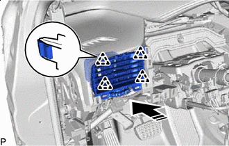
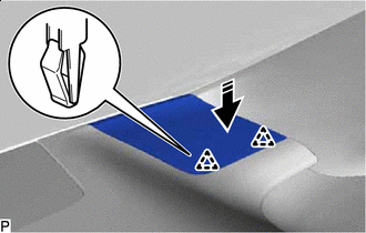
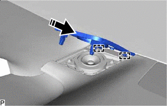
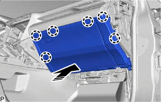
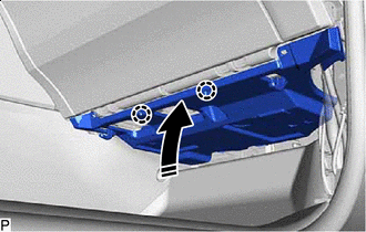
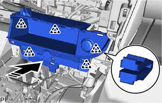
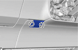
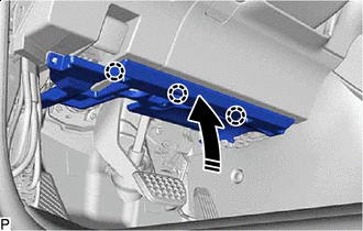
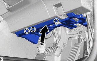
Install the instrument panel safety pad sub-assembly with the 7 bolts <C>, 2 bolts <A> and nut <G>.
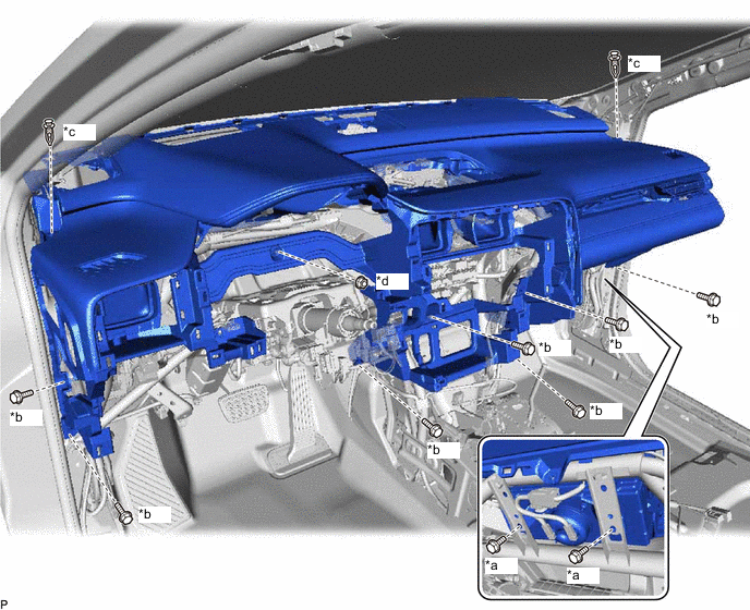
*a Bolt <A> *b Bolt <C> *c Clip *d Nut <G> - Torque:
- Bolt<A>
- 20 N*m { 204 kgf*cm, 15 ft.*lbf }
-
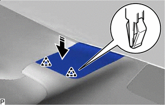
Install the 2 clips.
-
Engage each clamp.
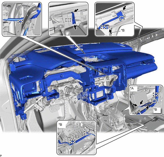
*A w/ Telematics Transceiver *B w/ Telematics Transceiver except G-BOOK -
Connect each connector.
-
-
CONNECT NO. 2 INSTRUMENT PANEL WIRE
-
INSTALL FRONT NO. 2 CONSOLE BOX INSERT
-
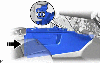
Install in this Direction Engage the guide to install the front No. 2 console box insert as shown in the illustration.
-
Install the 4 screws <E>.
-
Install the clip.
-
-
INSTALL FRONT NO. 1 CONSOLE BOX INSERT
-
Install in this Direction Engage the 3 guides to install the front No. 1 console box insert as shown in the illustration.
-
Install the 2 screws <E>.
-
Install the clip.
-
-
INSTALL NO. 2 INSTRUMENT CLUSTER MOULDING
-
w/ Interior Illumination:
-
Connect the connector.
-
-
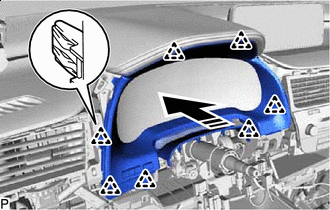
Install in this Direction Engage the 6 clips to install the No. 2 instrument cluster moulding as shown in the illustration.
-
-
INSTALL NO. 1 INSTRUMENT PANEL REGISTER ASSEMBLY
-
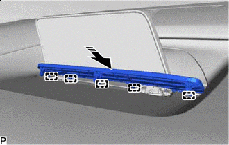
Install in this Direction Engage the 4 clips to install the No. 1 instrument panel register assembly as shown in the illustration.
-
-
INSTALL FRONT PILLAR GARNISH RH
-
INSTALL FRONT NO. 2 SPEAKER ASSEMBLY (for RH Side)
-
INSTALL NO. 2 INSTRUMENT PANEL SPEAKER PANEL SUB-ASSEMBLY
-

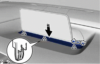
Install in this Direction Engage the 2 guides as shown in the illustration.
-
Install in this Direction Engage the 2 clips to install the No. 2 instrument panel speaker panel sub-assembly as shown in the illustration.
-
-
INSTALL FRONT NO. 3 SPEAKER ASSEMBLY
-
INSTALL NO. 1 SPEAKER OPENING COVER ASSEMBLY
-
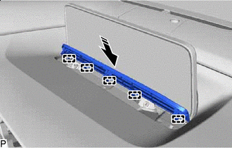
Install in this Direction Engage the 4 clips to install the No. 1 speaker opening cover assembly as shown in the illustration.
-
-
INSTALL FRONT PILLAR GARNISH LH
-
INSTALL FRONT NO. 2 SPEAKER ASSEMBLY (for LH Side)
-
INSTALL NO. 1 INSTRUMENT PANEL SPEAKER PANEL SUB-ASSEMBLY
-
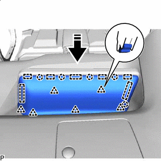
Install in this Direction Engage the 2 guides as shown in the illustration.
-
Install in this Direction Engage the 2 clips to install the No. 1 instrument panel speaker panel sub-assembly as shown in the illustration.
-
-
INSTALL GLOVE COMPARTMENT DOOR ASSEMBLY
-
Engage the clamp.
-
Connect the connector.
-
Install in this Direction Engage the 6 claws as shown in the illustration.
-
Install the 2 bolts <B> or <C>.
-
Open the glove compartment door assembly.
-
Install the glove compartment door assembly with the 3 screws <E>.
-
Close the glove compartment door assembly.
-
-
INSTALL NO. 2 INSTRUMENT PANEL UNDER COVER SUB-ASSEMBLY
-
Connect the connector.
-
Install in this Direction Engage the 2 guides as shown in the illustration.
-
Install in this Direction Engage the 2 claws as shown in the illustration.
-
Install the No. 2 instrument panel under cover sub-assembly with the 2 screws <D>.
-
-
INSTALL COWL SIDE TRIM BOARD RH
-
INSTALL FRONT DOOR SCUFF PLATE RH
-
INSTALL INSTRUMENT PANEL GARNISH RH
-
w/ Airbag Cut Off Switch:
-
Connect the connector.
-
-
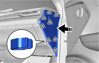
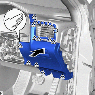
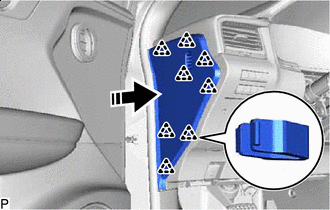
Install in this Direction Engage the 8 clips to install the instrument panel garnish RH as shown in the illustration.
-
-
INSTALL MULTI-DISPLAY ASSEMBLY (for 8 Inch Display)
-
INSTALL ACCESSORY METER ASSEMBLY (for 12.3 Inch Display)
-
INSTALL INSTRUMENT PANEL FINISH PANEL SUB-ASSEMBLY (for 8 Inch Display)
-
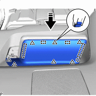
Install in this Direction Engage the 4 guides, 7 clips and claw to install the instrument panel finish panel sub-assembly as shown in the illustration.
-
-
INSTALL CENTER INSTRUMENT CLUSTER FINISH PANEL SUB-ASSEMBLY (for 8 Inch Display)
-
Install in this Direction Engage the 5 guides as shown in the illustration.
-
Install in this Direction Engage the guide, 2 claws and 3 clips to install the center instrument cluster finish panel sub-assembly as shown in the illustration.
-
-
INSTALL INSTRUMENT PANEL FINISH PANEL SUB-ASSEMBLY (for 12.3 Inch Display)
-
Install in this Direction Engage the 7 guides, 6 clips and 5 claws to install the instrument panel finish panel sub-assembly as shown in the illustration.
-
-
INSTALL CENTER INSTRUMENT CLUSTER FINISH PANEL SUB-ASSEMBLY (for 12.3 Inch Display)
-
Install in this Direction Engage the 5 guides as shown in the illustration.
-
Install in this Direction Engage the 3 clips to install the center instrument panel finish panel sub-assembly as shown in the illustration.
-
-
INSTALL CONSOLE BOX ASSEMBLY
-
Connect each connector.
-
Install in this Direction Engage the 5 clips to install the console box assembly as shown in the illustration.
-
-
INSTALL COOLER (ROOM TEMP. SENSOR) THERMISTOR
-
INSTALL RADIO RECEIVER ASSEMBLY WITH REGISTER
-
INSTALL COMBINATION METER ASSEMBLY
-
INSTALL INSTRUMENT CLUSTER FINISH PANEL SUB-ASSEMBLY
-
Connect the connector.
-
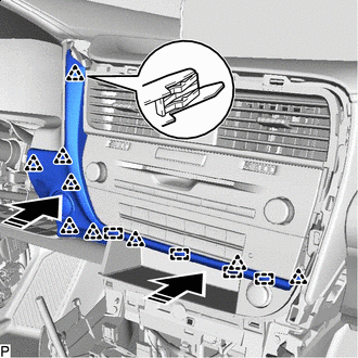
Install in this Direction Engage the 7 clips to install the instrument cluster finish panel sub-assembly as shown in the illustration.
-
-
INSTALL LOWER NO. 1 INSTRUMENT PANEL AIRBAG ASSEMBLY
-
INSTALL LOWER INSTRUMENT FINISH PANEL SUB
-
Connect the connector.
-
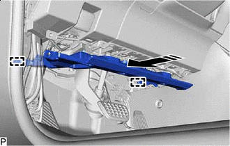
Install in this Direction Engage the 4 guides and 9 clips to install the lower instrument finish panel sub as shown in the illustration.
-
-
INSTALL LOWER INSTRUMENT PANEL FINISH PANEL SUB-ASSEMBLY
-
Connect each connector.
-
for LHD:
-
Install in this Direction Engage the 11 clips and 3 claws to install the lower instrument panel finish panel sub-assembly as shown in the illustration.
-
Install the 2 screws <D>.
-
Engage the 2 claws to connect the instrument panel hole cover.
-
-
for RHD:
-
Install in this Direction Engage the 12 clips and 3 claws to install the lower instrument panel finish panel sub-assembly as shown in the illustration.
-
-
-
CONNECT HOOD LOCK CONTROL LEVER SUB-ASSEMBLY
-
Engage the claw and 2 guides to connect the hood lock control lever sub-assembly.
-
-
INSTALL NO. 1 INSTRUMENT PANEL UNDER COVER SUB-ASSEMBLY
-
Engage the 2 claws to connect the DLC3 connector.
-
Engage the clamp.
-
Connect the connector.
-
for LHD:
-
Install in this Direction Engage the 2 guides as shown in the illustration.
-
Install in this Direction Engage the 3 claws as shown in the illustration.
-
-
for RHD:
-
Install in this Direction Engage the guide as shown in the illustration.
-
Install in this Direction Engage the 3 claws as shown in the illustration.
-
-
Install the No. 1 instrument panel under cover sub-assembly with the 2 screws <D>.
-
-
INSTALL COWL SIDE TRIM BOARD LH
-
INSTALL FRONT DOOR SCUFF PLATE LH
-
INSTALL INSTRUMENT PANEL GARNISH LH
-
Install in this Direction Engage the 8 clips to install the instrument panel garnish LH as shown in the illustration.
-
-
INSTALL CONSOLE BOX ASSEMBLY
-
INSTALL HEADLIGHT DIMMER SWITCH ASSEMBLY