TRANSFER ASSEMBLY REMOVAL

CAUTION / NOTICE / HINT
The necessary procedures (adjustment, calibration, initialization, or registration) that must be performed after parts are removed and installed, or replaced during transfer assembly removal/installation are shown below.
| Replacement Part or Procedure | Necessary Procedure | Effect/Inoperative when not Performed | Link |
|---|---|---|---|
| Disconnect cable from negative battery terminal | Memorize steering angle neutral point |
|
|
| Initialize back door lock | Power door lock control system | ||
|
Inspection After Repair |
|
|
| Replacement of CVT fluid | ATF thermal degradation estimate reset | The value of the Data List item "ATF Thermal Degradation Estimate" is not estimated correctly | |
| Replacement of continuously variable transaxle assembly | Perform the following procedures in the order shown:
|
Deterioration of fuel efficiency | |
| Front wheel alignment adjustment | Perform the following procedures in the order shown:
|
|
|
| Suspension, tires, etc. (The vehicle height changes because of suspension or tire replacement) |
Initialize No. 1 headlight ECU sub-assembly LH | Automatic headlight beam level control system |
-
*1: When performing learning using the GTS.
CAUTION:
-
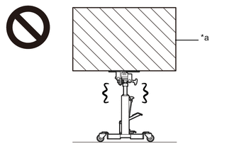
*a Heavy object exceeding the capacity of the transmission jack Because the continuously variable transaxle assembly is extremely heavy, make sure to follow the work procedures described in the repair manual.
-
If work is not performed according to the procedures described in the repair manual, there is a danger that the transmission jack could drop and components could fall down.
-
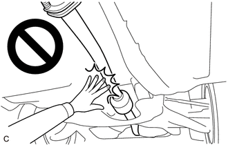
When the engine is hot, do not touch high-temperature areas such as the engine or exhaust pipe.
-
Touching high-temperature areas such as the engine and exhaust pipe could result in burns.
PROCEDURE
-
REMOVE CONTINUOUSLY VARIABLE TRANSAXLE ASSEMBLY
-
REMOVE TRANSFER ASSEMBLY
-
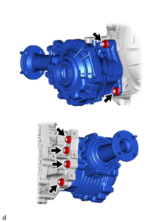
Remove the 6 nuts and transfer assembly from the transaxle.
-
-
REMOVE TRANSFER AND TRANSAXLE SETTING STUD BOLT
Tech Tips
It is not necessary to remove the transfer and transaxle setting stud bolts unless they are being replaced.
-
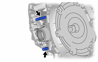
Remove the 2 transfer and transaxle setting stud bolts.
-