AIR CONDITIONING UNIT(for VALEO Made) INSTALLATION
CAUTION / NOTICE / HINT
Tech Tips
-
Use the same procedure for RHD and LHD vehicles.
-
The procedure listed below is for LHD vehicles
PROCEDURE
-
INSTALL LOWER DEFROSTER NOZZLE ASSEMBLY
-
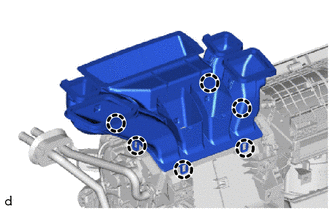
Engage the claws to install the lower defroster nozzle assembly.
-
-
TEMPORARILY INSTALL AIR CONDITIONER UNIT ASSEMBLY
-
Temporarily install the air conditioner unit assembly to the instrument panel reinforcement assembly with the 3 bolts.
-
-
INSTALL INSTRUMENT PANEL REINFORCEMENT ASSEMBLY WITH AIR CONDITIONER UNIT ASSEMBLY
Note
When installing the air conditioner unit assembly, eliminate static electricity by touching the vehicle body to prevent the components from being damaged.
-
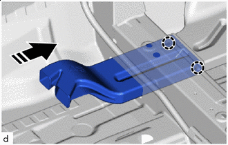
Engage the guides to install the instrument panel reinforcement assembly with air conditioner unit assembly as shown in the illustration.
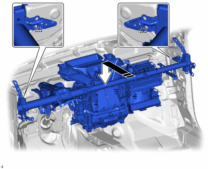

Install in this Direction - - -
Connect 2 connectors.
-
Engage the clamps.
-
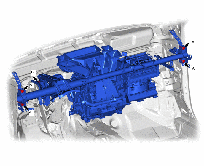
Install the 5 bolts.
- Torque:
- Bolt A
- 25 N*m { 255 kgf*cm, 18 ft.*lbf }
- Bolt B
- 23.6 N*m { 241 kgf*cm, 17 ft.*lbf }
-
Temporarily install the nut.
-
Install the 2 bolts.
- Torque:
- 25 N*m { 255 kgf*cm, 18 ft.*lbf }
-
-
CONNECT DRAIN COOLER HOSE
-
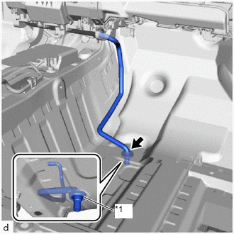
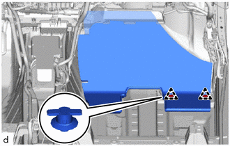
*1 Cooler Unit Drain Hose Grommet Connect the drain cooler hose.
Note
If the cooler unit drain hose grommet is disconnected from the vehicle body while connecting the drain cooler hose, make sure to replace it with a new one. Failure to do so may cause water ingress.
-
-
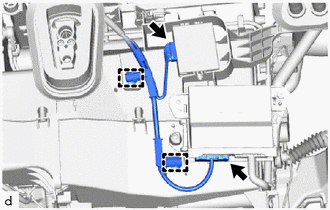
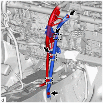
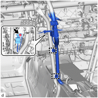
CONNECT INSTRUMENT PANEL WIRE
-
for LHD:
-
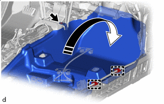
Engage clamps and hook to connect the instrument panel wire.
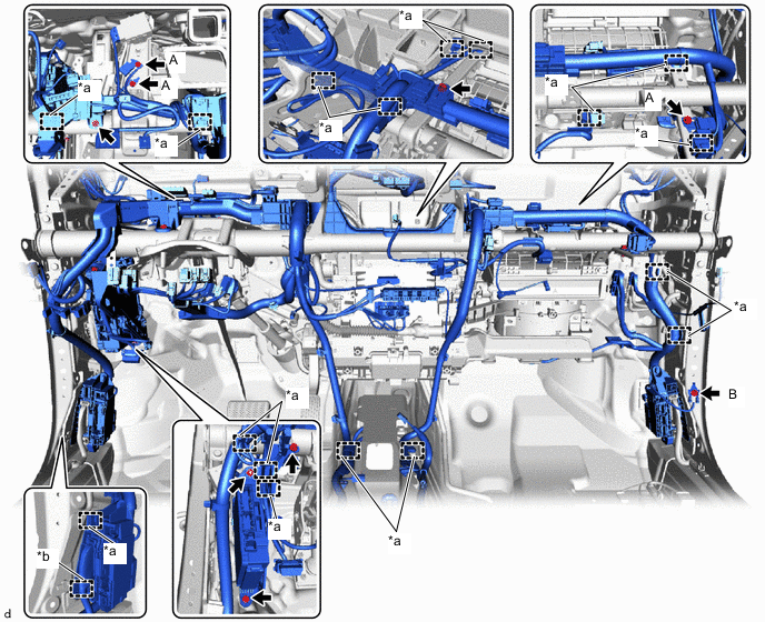
*a Clamp *b Hook -
Install the instrument panel junction block assembly with main body ECU with the bolt and nut.
- Torque:
- 8.0 N*m { 82 kgf*cm, 71 in.*lbf }
-
Install the 4 ground wires with the 4 bolts.
- Torque:
- Bolt A
- 10.5 N*m { 107 kgf*cm, 8 ft.*lbf }
- Bolt B (Part No. 90119-06995)
- 10.5 N*m { 107 kgf*cm, 8 ft.*lbf }
- Bolt B (Part No. 90119-W0017)
- 8.5 N*m { 87 kgf*cm, 75 in.*lbf }
-
Install the bolt and screw.
- Torque:
- Bolt
- 8.0 N*m { 82 kgf*cm, 71 in.*lbf }
-
Connect each connector.
-
-
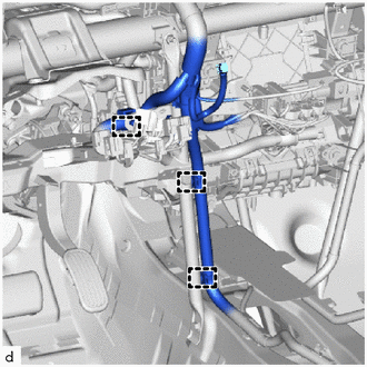
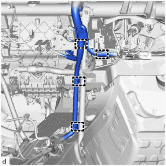
for RHD:
-
Engage clamps and hook to connect the instrument panel wire.
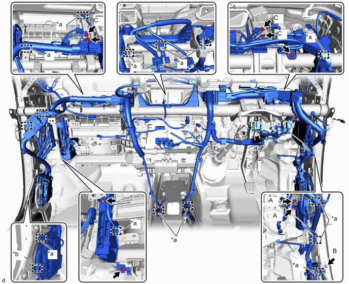
*a Clamp *b Hook -
Install the instrument panel junction block assembly with main body ECU with the bolt and nut.
- Torque:
- 8.0 N*m { 82 kgf*cm, 71 in.*lbf }
-
Install the 2 nuts A.
- Torque:
- 12.5 N*m { 127 kgf*cm, 9 ft.*lbf }
-
Install the 4 ground wires with the 4 bolts.
- Torque:
- Bolt B (Part No. 90119-06995)
- 10.5 N*m { 107 kgf*cm, 8 ft.*lbf }
- Bolt B (Part No. 90119-W0017)
- 8.5 N*m { 87 kgf*cm, 75 in.*lbf }
- Bolt C
- 10.5 N*m { 107 kgf*cm, 8 ft.*lbf }
-
Install the bolt and screw.
- Torque:
- Bolt
- 8.0 N*m { 82 kgf*cm, 71 in.*lbf }
-
Connect each connector.
-
-
-
INSTALL NO. 3 INSTRUMENT PANEL TO COWL BRACE SUB-ASSEMBLY
-
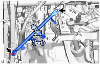
Install the No. 3 instrument panel to cowl brace sub-assembly with the nut and bolt.
- Torque:
- Bolt
- 10 N*m { 102 kgf*cm, 7 ft.*lbf }
- Nut
- 6.0 N*m { 61 kgf*cm, 53 in.*lbf }
-
Engage the clamp and claws.
-
-
INSTALL NO. 2 INSTRUMENT PANEL BRACE SUB-ASSEMBLY
-
for LHD:
-
Install the No. 2 instrument panel brace sub-assembly with the bolt and nut.
- Torque:
- Bolt
- 20 N*m { 204 kgf*cm, 15 ft.*lbf }
- Nut
- 18 N*m { 184 kgf*cm, 13 ft.*lbf }
-
Temporarily install the screw.
Tech Tips
Do not fully tighten the screw.
-
Install the ground wire with the bolt.
- Torque:
- 10.5 N*m { 107 kgf*cm, 8 ft.*lbf }
-
Engage the clamps to connect the wire harness.
-
-
for RHD:
-
Install the No. 2 instrument panel brace sub-assembly with the bolt and nut.
- Torque:
- Bolt
- 20 N*m { 204 kgf*cm, 15 ft.*lbf }
- Nut
- 18 N*m { 184 kgf*cm, 13 ft.*lbf }
-
Temporarily install the screw.
Tech Tips
Do not fully tighten the screw.
-
Install the ground wire with the bolt.
- Torque:
- 10.5 N*m { 107 kgf*cm, 8 ft.*lbf }
-
Engage the clamps to connect the wire harness.
-
-
-
INSTALL NO. 1 INSTRUMENT PANEL BRACE SUB-ASSEMBLY
-
for LHD:
-
Install the No. 1 instrument panel brace sub-assembly with the bolt and 2 nuts.
- Torque:
- Bolt
- 20 N*m { 204 kgf*cm, 15 ft.*lbf }
- Nut
- 18 N*m { 184 kgf*cm, 13 ft.*lbf }
-
Temporarily install the screw.
Tech Tips
Do not fully tighten the screw.
-
Engage the clamps to connect the wire harness.
-
-
for RHD:
-
Install the No. 1 instrument panel brace sub-assembly with the bolt and 2 nuts.
- Torque:
- Bolt
- 20 N*m { 204 kgf*cm, 15 ft.*lbf }
- Nut
- 18 N*m { 184 kgf*cm, 13 ft.*lbf }
-
Temporarily install the screw.
Tech Tips
Do not fully tighten the screw.
-
Engage the clamps to connect the wire harness.
-
-
w/ PTC Heater:
-
Install the bolt to connect the ground wire.
- Torque:
- 10.5 N*m { 107 kgf*cm, 8 ft.*lbf }
-
-
Install the relay block assembly with the 2 nuts.
- Torque:
- 8.0 N*m { 82 kgf*cm, 71 in.*lbf }
-
-
INSTALL AIR CONDITIONER UNIT ASSEMBLY
-
for LHD:
-
Tighten the 3 bolts, 2 screws and nut in the order shown in the illustration to install the air conditioner unit.
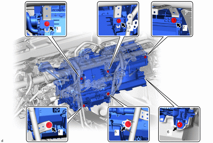
- Torque:
- 9.8 N*m { 100 kgf*cm, 87 in.*lbf }
-
-
for RHD:
-
Tighten the 3 bolts, 2 screws and nut in the order shown in the illustration to install the air conditioner unit.
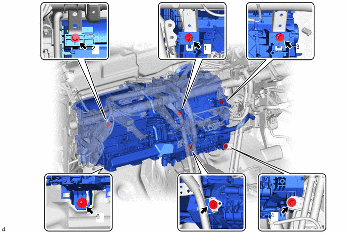
- Torque:
- 9.8 N*m { 100 kgf*cm, 87 in.*lbf }
-
-
-
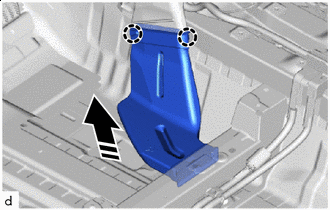
INSTALL REAR NO. 1 AIR DUCT (w/ Rear Air Duct)
-
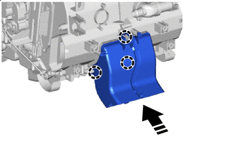
Install in this Direction Engage the claws to install the rear No. 1 air duct as shown in the illustration.
-
-
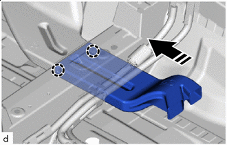
INSTALL REAR NO. 2 AIR DUCT (w/ Rear Air Duct)
-
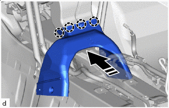
Install in this Direction Engage the claws to install the rear No. 2 air duct as shown in the illustration.
-
-
INSTALL REAR NO. 3 AIR DUCT (w/ Rear Air Duct)
-
Install in this Direction Engage the claws to install the rear No. 3 air duct as shown in the illustration.
-
-
INSTALL REAR NO. 4 AIR DUCT (w/ Rear Air Duct)
-
Install in this Direction Engage the claws to install the rear No. 4 air duct as shown in the illustration.
-
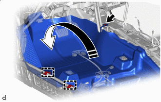
Install in this Direction Install the front floor carpet assembly to its original position as shown in the illustration.
-
Engage the clamps.
-
Install the clip.
-
Install the 2 front floor carpet clips.
-
-
INSTALL REAR NO. 5 AIR DUCT (w/ Rear Air Duct)
-
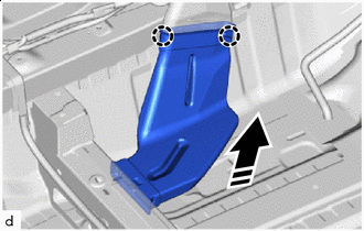
Install in this Direction Engage the claws to install the rear No. 5 air duct as shown in the illustration.
-
-
INSTALL REAR NO. 6 AIR DUCT (w/ Rear Air Duct)
-
Install in this Direction Engage the claws to install the rear No. 6 air duct as shown in the illustration.
-
-
INSTALL NO. 3 DASH PANEL INSULATOR PAD
-
Engage the clips to install the No. 3 dash panel insulator pad.
-
Install in this Direction Install the front floor carpet assembly to its original position as shown in the illustration.
-
Engage the clamps.
-
Install the clip.
-
Install the 2 front floor carpet clips.
-
-
INSTALL COOLER THERMISTOR (ROOM TEMPERATURE SENSOR)
-
Connect the aspirator and connector to install the cooler thermistor (room temperature sensor).
-
-
INSTALL ECU INTEGRATION BOX RH (for LHD)
-
INSTALL ECU INTEGRATION BOX LH (for RHD)
-
INSTALL CLEARANCE WARNING ECU ASSEMBLY (w/ Clearance Sonar System)
-
INSTALL WINDSHIELD WIPER RELAY ASSEMBLY
-
INSTALL STEERING COLUMN ASSEMBLY
-
INSTALL INSTRUMENT PANEL SAFETY PAD SUB-ASSEMBLY
-
INSTALL FRONT SEAT ASSEMBLY LH
-
INSTALL FRONT SEAT ASSEMBLY RH
Tech Tips
Use the same procedure as for the LH side.
-
CONNECT COOLER REFRIGERANT LIQUID PIPE A
-
Remove the vinyl tape from the cooler refrigerant liquid pipe A.
-
Apply sufficient compressor oil to a new O-ring and fitting surface of the cooler refrigerant liquid pipe A.
Compressor Oil VC100YF or equivalent -
Install the O-ring to the cooler refrigerant liquid pipe A.
Note
Keep the O-ring and O-ring fitting surface free of foreign matter.
-
Connect the cooler refrigerant liquid pipe A.
-
-
CONNECT SUCTION PIPE SUB-ASSEMBLY
-
Remove the vinyl tape from the suction pipe sub-assembly and cooler refrigerant liquid pipe A.
-
Apply sufficient compressor oil to a new 2 O-rings and fitting surface of the suction pipe sub-assembly and cooler refrigerant liquid pipe A.
Compressor Oil VC100YF or equivalent -
Install the O-ring to the suction pipe sub-assembly and cooler refrigerant liquid pipe A.
Note
Keep the O-ring and O-ring fitting surface free of foreign matter.
-
Connect the suction pipe sub-assembly and cooler refrigerant liquid pipe A.
-
Install the bolt.
- Torque:
- 9.8 N*m { 100 kgf*cm, 87 in.*lbf }
-
-
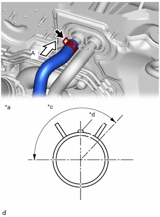
CONNECT INLET HEATER WATER HOSE
-
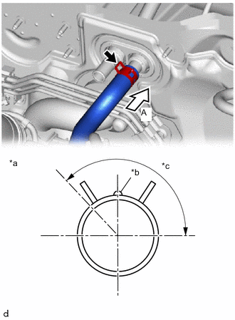
*a View A *b Marking (White) *c Clip Installation Angle (135°) Connect the inlet heater water hose with the marking (white) facing up and engage the clip within the area shown in the illustration.
Note
Do not apply excessive force to the inlet heater water hose.
-
-
CONNECT OUTLET HEATER WATER HOSE
-
*a View A *b Marking (White) *c Clip Installation Angle (135°) Connect the outlet heater water hose with the marking (white) facing up and engage the clip within the area shown in the illustration.
Note
Do not apply excessive force to the outlet heater water hose.
-
-
INSTALL OUTER COWL TOP PANEL SUB-ASSEMBLY (for LHD)
-
INSTALL OUTER COWL TOP PANEL SUB-ASSEMBLY (for RHD)
-
INSTALL COWL BODY MOUNTING REINFORCEMENT LH
-
INSTALL COWL BODY MOUNTING REINFORCEMENT RH
-
INSTALL WATER GUARD PLATE LH
-
INSTALL NO. 1 HEATER AIR DUCT SPLASH SHIELD SEAL
-
INSTALL WINDSHIELD WIPER MOTOR AND LINK ASSEMBLY
-
ADD ENGINE COOLANT (for 8NR-FTS)
-
ADD ENGINE COOLANT (for 3ZR-FAE)
-
INSPECT FOR COOLANT LEAK (for 8NR-FTS)
-
INSPECT FOR COOLANT LEAK (for 3ZR-FAE)
-
CHARGE AIR CONDITIONING SYSTEM WITH REFRIGERANT (for HFC-134a(R134a))
-
CHARGE AIR CONDITIONING SYSTEM WITH REFRIGERANT (for HFO-1234yf(R1234yf))
-
WARM UP ENGINE (for HFC-134a(R134a))
-
WARM UP ENGINE (for HFO-1234yf(R1234yf))
-
INSPECT FOR REFRIGERANT LEAK (for HFC-134a(R134a))
-
INSPECT FOR REFRIGERANT LEAK (for HFO-1234yf(R1234yf))
-
INITIALIZATION SERVO MOTOR