ELECTRONICALLY CONTROLLED BRAKE SYSTEM(w/ Vacuum Brake Booster), Diagnostic DTC:C1403, C1404
| DTC Code | DTC Name |
|---|---|
| C1403 | Rear Speed Sensor RH Malfunction |
| C1404 | Rear Speed Sensor LH Malfunction |
DESCRIPTION
Refer to DTCs C1415 and C1416.
| DTC No. | Detection Item | DTC Detection Condition | Trouble Area | Note |
|---|---|---|---|---|
| C1403 | Rear Speed Sensor RH Malfunction | Any of the following is detected:
|
|
- |
| C1404 | Rear Speed Sensor LH Malfunction | Any of the following is detected:
|
|
- |
-
*1: for AWD
-
*2: for 2WD
| Vehicle Condition | ||||||
|---|---|---|---|---|---|---|
| Pattern 1 | Pattern 2 | Pattern 3 | Pattern 4 | Pattern 5 | ||
| Diagnosis Condition | - | - | - | - | - | - |
| Malfunction Status | At a vehicle speed of 10 km/h (6 mph) or more, output voltage from one of the speed sensors is less than that from the other sensors*2 | ○ | - | - | - | - |
| At a vehicle speed of 10 km/h (6 mph) or more, output voltage from one of the speed sensors is less than that from the other sensors*1 | - | ○ | - | - | - | |
| At a vehicle speed less than 10 km/h (6 mph), output from one of the speed sensors is 0 km/h (0 mph) | - | - | ○ | - | - | |
| At a vehicle speed of 10 km/h (6 mph) or more, outputs from both front speed sensors are 0 km/h (0 mph)*2 | - | - | - | ○ | - | |
| At a vehicle speed of 10 km/h (6 mph) or more, outputs from both front speed sensors are 0 km/h (0 mph)*1 | - | - | - | - | ○ | |
| Detection Time | 15 seconds or more. | 30 seconds or more. | 1 second or more. | 15 seconds or more. | 30 seconds or more. | |
| Number of Trips | 1 trip | 1 trip | 1 trip | 1 trip | 1 trip | |
-
*1: for AWD
-
*2: for 2WD
Tech Tips
DTC will be output when conditions for either of the patterns in the table above are met.
PROCEDURE
-
CHECK REAR SPEED SENSOR INSTALLATION
-
Turn the engine switch off.
-
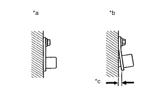
*a Normal *b Abnormal *c Clearance Check the speed sensor installation.
OK There is no clearance between the sensor and rear axle carrier. The installation bolt is tightened properly. Result Proceed to OK NG
NG 
INSTALL REAR SPEED SENSOR CORRECTLY Click here
OK 
-
-
CHECK REAR SPEED SENSOR (CHECK FOR FOREIGN MATTER)
-
Remove the rear speed sensor.
-
Check the rear speed sensor tip.
OK The sensor tip is free of scratches, oil, and foreign matter. Note
-
If there is oil or foreign matter on the speed sensor, clean the speed sensor.
-
If the speed sensor is damaged, replace the speed sensor with a new one.
-
Check the speed sensor signal after cleaning or replacement.
Result Proceed to OK NG -
NG
CLEAN OR REPLACE REAR SPEED SENSOR
OK
-
-
READ VALUE USING GTS (REAR SPEED SENSOR)
-
Connect the GTS to the DLC3.
-
Start the engine.
-
Select the Data List using the GTS.
Chassis > ABS/VSC/TRC > Data ListTester Display Measurement Item Range Normal Condition Diagnostic Note RR Wheel Speed Rear wheel speed sensor RH reading Min.: 0 km/h (0 mph), Max.: 326 km/h (202 mph) Vehicle stopped: 0 km/h (0 mph) When driving at constant speed: No large fluctuations RL Wheel Speed Rear wheel speed sensor LH reading Min.: 0 km/h (0 mph), Max.: 326 km/h (202 mph) Vehicle stopped: 0 km/h (0 mph) When driving at constant speed: No large fluctuations
Chassis > ABS/VSC/TRC > Data ListTester Display RR Wheel Speed RL Wheel Speed -
Check the speed value output from the speed sensor displayed on the GTS.
Tech Tips
Factors that affect the indicated vehicle speed include tire size, tire pressure, and tire wear. The speed indicated on the speedometer has an allowable margin of error. This can be tested using a speedometer tester (calibrated chassis dynamometer). For details about testing and the margin of error, see the reference chart.
OK The speed value output from the speed sensor displayed on the GTS is similar to the speed indicated on the speedometer. Result Proceed to OK NG
OK
USE SIMULATION METHOD TO CHECK Click here
NG
-
-
INSPECT SKID CONTROL SENSOR WIRE
-
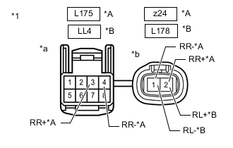
*A for RH *B for LH *1 Skid Control Sensor Wire *a Front view of wire harness connector
(to Vehicle Side Connector)
*b Front view of wire harness connector
(to Sensor Side Connector)
Install the rear speed sensor and the component with the speed sensor rotor.
-
Make sure that there is no looseness at the locking part and the connecting part of the connectors.
-
Disconnect the z24, L178, L175 and/or LL4 skid control sensor wire connector.
-
Measure the resistance according to the value(s) in the table below.
Standard Resistance for RH Tester Connection Condition Specified Condition z24 -2 (RR+) - L175 -3 (RR+) Always Below 1 Ω z24 -2 (RR+) - L175 -4 (RR-) Always 10 MΩ or higher z24 -2 (RR+) or L175 -3 (RR+) - Body ground Always 10 MΩ or higher z24 -1 (RR-) - L175 -4 (RR-) Always Below 1 Ω z24 -1 (RR-) - L175 -3 (RR+) Always 10 MΩ or higher z24 -1 (RR-) or L175 -4 (RR-) - Body ground Always 10 MΩ or higher for LH Tester Connection Condition Specified Condition L178 -2 (RL+) - LL4 -3 Always Below 1 Ω L178 -2 (RL+) - LL4 -4 Always 10 MΩ or higher L178 -2 (RL+) or LL4 -3 - Body ground Always 10 MΩ or higher L178 -1 (RL-) - LL4 -4 Always Below 1 Ω L178 -1 (RL-) - LL4 -3 Always 10 MΩ or higher L178 -1 (RL-) or LL4 -4 - Body ground Always 10 MΩ or higher Result Proceed to OK NG
NG
REPLACE SKID CONTROL SENSOR WIRE Click here
OK
-
-
CHECK HARNESS AND CONNECTOR (BRAKE ACTUATOR ASSEMBLY - SKID CONTROL SENSOR WIRE)
-
Make sure that there is no looseness at the locking part and the connecting part of the connector.
-
Disconnect the A9 skid control ECU (brake actuator assembly) connector.
-
Measure the resistance according to the value(s) in the table below.
Standard Resistance for RH Tester Connection Condition Specified Condition A9-16 (RR+) - L175-3 (RR+) Always Below 1 Ω A9-16 (RR+) or L175-3 (RR+) - Body ground Always 10 kΩ or higher A9-15 (RR-) - L175-4 (RR-) Always Below 1 Ω A9-15 (RR-) or L175-4 (RR-) - Body ground Always 10 kΩ or higher for LH Tester Connection Condition Specified Condition A9-29 (RL+) - LL4 -3 Always Below 1 Ω A9-29 (RL+) or LL4 -3 - Body ground Always 10 kΩ or higher A9-28 (RL-) - LL4 -4 Always Below 1 Ω A9-28 (RL-) or LL4 -4 - Body ground Always 10 kΩ or higher Result Proceed to OK NG
NG
REPAIR OR REPLACE HARNESS OR CONNECTOR
OK
-
-
CHECK REAR SPEED SENSOR ROTOR (CHECK FOR FOREIGN MATTER)
-
Remove the component with the speed sensor rotor.
-
Check the speed sensor rotor.
OK The rotor is free of scratches, oil, and foreign matter. Note
-
If there is oil or foreign matter on the speed sensor rotor, clean the speed sensor rotor.
-
If the speed sensor rotor is damaged, replace the speed sensor rotor with a new one.
-
Check the speed sensor signal after cleaning or replacement.
Tech Tips
-
The rear speed sensor rotor is incorporated into the rear axle hub and bearing assembly.
-
If the rear speed sensor rotor needs to be replaced, replace it together with the rear axle hub and bearing assembly.
Result Result Proceed to OK A NG (The speed sensor rotor is damaged.) B NG (There is foreign matter on the speed sensor rotor.) C -
A
REPLACE REAR SPEED SENSOR Click here
B
REPLACE REAR AXLE HUB AND BEARING ASSEMBLY Click here
C
CLEAN REAR SPEED SENSOR ROTOR
-