AUDIO AND VISUAL SYSTEM Radio Broadcast cannot be Received (Bad Reception)
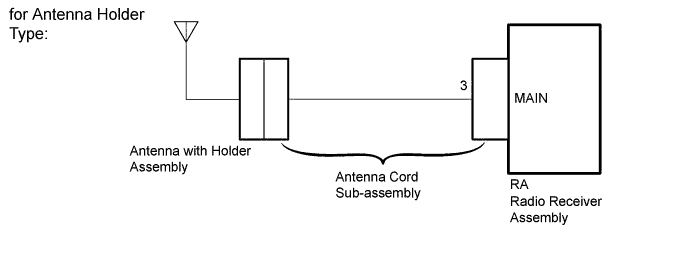
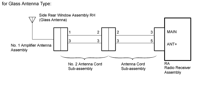
WIRING DIAGRAM
INSPECTION PROCEDURE
Note
Check that the wire harness is properly installed and does not have any sharp bends, pinching or loose connections Click here.
PROCEDURE
-
CHECK IF RADIO AUTO-SEARCH FUNCTIONS PROPERLY
-
Check the radio automatic station search function by activating it.
OK Automatic station search function stops on a station.
NG 
CHECK OPTIONAL COMPONENTS Click here
OK 
USE SIMULATION METHOD TO CHECK Click here
-
-
CHECK OPTIONAL COMPONENTS
-
Check if any optional components that may decrease reception capacity, such as sunshade film or a telephone antenna, are not installed.
Note
Do not remove optional components without permission of the customer.
OK Optional components are not installed. Result Result Proceed to OK (for Antenna Holder Type) A OK (for Glass Antenna Type) B NG C
B
CHECK RADIO ANTENNA Click here
C
INSPECT SIDE REAR WINDOW ASSEMBLY RH (GLASS ANTENNA) Click here
A
REMOVE OPTIONAL COMPONENTS (SEE NOTICE ABOVE)
-
-
CHECK RADIO ANTENNA
-
Turn the ignition switch to ACC with radio receiver assembly connector connected.
-
Turn on the radio and turn into AM mode.
-
Place a screwdriver, thin wire or other metal object on the antenna with holder assembly and check that noise can be heard from the speakers.
OK Noise Occurs.
NG 
REPLACE RADIO RECEIVER ASSEMBLY Click here
OK 
-
-
CHECK ANTENNA CORD SUB-ASSEMBLY
-
Disconnect the antenna plug from the antenna with holder assembly.
-
Turn the ignition switch to ACC with radio receiver assembly connector connected.
-
Turn on the radio and turn into AM mode.
-
Place a screwdriver, thin wire or other metal object on the antenna with holder assembly antenna jack and check that noise can be heard from the speakers.
OK Noise Occurs.
NG
CHECK RADIO RECEIVER ASSEMBLY (ANTENNA) Click here
OK
REPLACE ANTENNA WITH HOLDER ASSEMBLY Click here
-
-
CHECK RADIO RECEIVER ASSEMBLY (ANTENNA)
-
Remove the antenna connector from the radio receiver assembly.
-
Turn the ignition switch to ACC with radio receiver assembly connector connected.
-
Turn on the radio and turn into AM mode.
-
Place a screwdriver, thin wire or other metal object on the radio receiver assembly antenna jack and check that noise can be heard from the speakers.
OK Noise Occurs.
NG
REPLACE RADIO RECEIVER ASSEMBLY Click here
OK
-
-
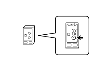
INSPECT RADIO RECEIVER ASSEMBLY
-
Disconnect the RA radio receiver assembly connector.
-
Measure the voltage according to the value(s) in the table below.
Standard Voltage Tester Connection Switch Condition Specified Condition 3 (MAIN) - Body ground Ignition switch ACC, radio switch on and FM or AM selected 11 to 14 V
NG
REPLACE RADIO RECEIVER ASSEMBLY Click here
OK
-
-
CHECK ANTENNA CORD SUB-ASSEMBLY
-
Replace the antenna cord sub-assembly with known good one and check if radio broadcasting can be received normally Click here.
OK Radio broadcasts can be received normally.
NG
CHECK ANTENNA WITH HOLDER ASSEMBLY Click here
OK
END (ANTENNA CORD SUB-ASSEMBLY IS DEFECTIVE)
-
-
CHECK ANTENNA WITH HOLDER ASSEMBLY
-
Check that the antenna with holder assembly is securely installed.
OK The antenna with holder assembly is installed properly.
NG
REINSTALL ANTENNA WITH HOLDER ASSEMBLY Click here
OK
-
-
CHECK ANTENNA WITH HOLDER ASSEMBLY
-
Replace the antenna with holder assembly and check if radio broadcasts can be received normally Click here.
OK Radio broadcasts can be received normally.
NG
REPLACE RADIO RECEIVER ASSEMBLY Click here
OK
END (ANTENNA WITH HOLDER ASSEMBLY IS DEFECTIVE)
-
-
INSPECT SIDE REAR WINDOW ASSEMBLY RH (GLASS ANTENNA)
-
Inspect the side rear window assembly RH (glass antenna) Click here.
NG
REPAIR OR REPLACE SIDE REAR WINDOW ASSEMBLY RH Click here
OK
-
-
CHECK RADIO RECEIVER ASSEMBLY (ANTENNA)
-
Remove the antenna connector from the radio receiver assembly.
-
Turn the ignition switch to ACC with the radio receiver assembly connector connected.
-
Turn on the radio and turn into AM mode.
-
Place a screwdriver, thin wire or other metal object on the radio receiver assembly antenna jack and check that noise can be heard from the speakers.
OK Noise occurs.
NG
REPLACE RADIO RECEIVER ASSEMBLY Click here
OK
-
-
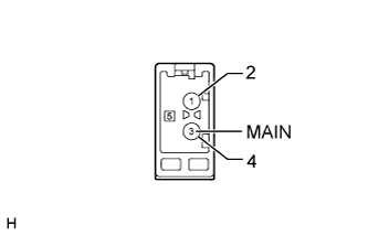
INSPECT RADIO RECEIVER ASSEMBLY
-
Disconnect the RA radio receiver assembly connector.
-
Measure the voltage according to the value(s) in the table below.
Standard Voltage Tester Connection Switch Condition Specified Condition 5 (ANT+) - Body ground Ignition switch ACC, radio switch on and FM or AM selected 11 to 14 V
NG
REPLACE RADIO RECEIVER ASSEMBLY Click here
OK
-
-
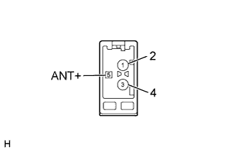
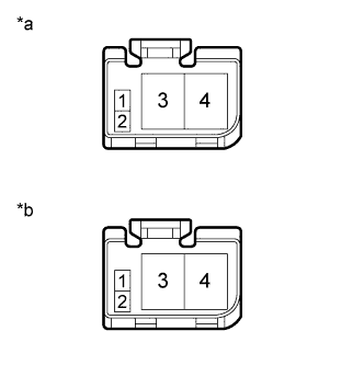
CHECK ANTENNA CORD SUB-ASSEMBLY
-
Text in Illustration *a Front view of wire harness connector
(to Radio Receiver Assembly)
*b Front view of wire harness connector
(to No. 2 Antenna Cord Sub-assembly)
Disconnect the radio receiver assembly connector.
-
Remove the antenna connector from the No. 2 antenna cord sub-assembly.
-
Measure the resistance according to the value(s) in the table below.
Standard Resistance Tester Connection Condition Specified Condition RA-3 (MAIN) - 2 Always Below 1 Ω RA-5 (ANT+) - 3 Always Below 1 Ω RA-3 (MAIN) - Body ground Always 10 kΩ or higher RA-5 (ANT+) - Body ground Always 10 kΩ or higher
NG
REPLACE ANTENNA CORD SUB-ASSEMBLY Click here
OK
-
-
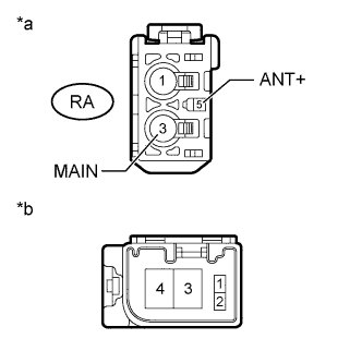
CHECK NO. 2 ANTENNA CORD SUB-ASSEMBLY
-
Text in Illustration *a Front view of wire harness connector
(to Antenna Cord Sub-assembly)
*b Front view of wire harness connector
(to No. 1 Amplifier Antenna Assembly)
Remove the antenna connector from the antenna cord sub-assembly.
-
Remove the antenna connector from the No. 1 amplifier antenna assembly.
-
Measure the resistance according to the value(s) in the table below.
Standard Resistance Tester Connection Condition Specified Condition 2 - 1 Always Below 1 Ω 3 - 3 Always Below 1 Ω 2 - Body ground Always 10 kΩ or higher 3 - Body ground Always 10 kΩ or higher
NG
REPLACE NO. 2 ANTENNA CORD SUB-ASSEMBLY Click here
OK
-
-
REPLACE NO. 1 AMPLIFIER ANTENNA ASSEMBLY
-
Replace the No. 1 amplifier antenna assembly with known good one and check if radio broadcasts can be received normally Click here.
OK Radio broadcasts can be received normally.
NG
REPLACE RADIO RECEIVER ASSEMBLY Click here
OK
END (NO. 1 AMPLIFIER ANTENNA ASSEMBLY IS DEFECTIVE)
-