NAVIGATION SYSTEM TERMINALS OF ECU
Tech Tips
Check from the rear of the connector while it is connected to the components.
-
RADIO AND DISPLAY RECEIVER ASSEMBLY
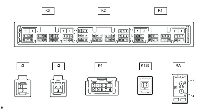
Terminal No. (Symbol) Wiring Color Terminal Description Condition Specified Condition K4-1 (FR+) - K3-1 (GND1) LA-LG - BR*3
W - BR*4
Sound signal (Front right)*3
Sound signal (Right)*4
Audio system playing A waveform synchronized with sound signals is output K4-2 (FL+) - K3-1 (GND1) LA-B - BR*3
B - BR*4
Sound signal (Front left)*3
Sound signal (Left)*4
Audio system playing A waveform synchronized with sound signals is output K4-3 (RL+) - K3-1 (GND1) LA-G - BR*3
Y - BR*4
Sound signal (Rear left)*3
Voice signal*4
Audio system playing*3
Voice guidance sounding*4
A waveform synchronized with sound signals is output*3
A waveform synchronized with voice signals is output*4
K4-4 (RR+) - K3-1 (GND1)*3 LA-R - BR Sound signal (Rear right) Audio system playing A waveform synchronized with sound signals is output K4-6 (FR-) - K3-1 (GND1) LA-L - BR*3
R - BR*4
Sound signal (Front right)*3
Sound signal (Right)*4
Audio system playing A waveform synchronized with sound signals is output K4-7 (FL-) - K3-1 (GND1) LA-R - BR*3
G - BR*4
Sound signal (Front left)*3
Sound signal (Left)*4
Audio system playing A waveform synchronized with sound signals is output K4-8 (RL-) - K3-1 (GND1) LA-GR - BR*3
BR - BR*4
Sound signal (Rear left)*3
Voice signal*4
Audio system playing*3
Voice guidance sounding*4
A waveform synchronized with sound signals is output*3
A waveform synchronized with voice signals is output*4
K4-9 (RR-) - K3-1 (GND1)*3 LA-G - BR Sound signal (Rear right) Audio system playing A waveform synchronized with sound signals is output K3-1 (GND1) - Body ground BR - Body ground Ground Always Below 1 V K3-4 (+B1) - K3-1 (GND1) LG - BR Power source (+B) Always 11 to 14 V K3-5 (TX1+)*1,*4 L*1
B*4
AVC-LAN communication signal - - K3-6 (TX1-)*1,*4 GR*1
W*4
AVC-LAN communication signal - - K3-10 (AGND) - Body ground Shielded - Body ground Shield ground Always Below 1 V K3-11 (VAL+) - K3-13 (VA-) B - R Sound signal (Left) External device playing (When stereo jack used) A waveform synchronized with sound signals is output K3-12 (VAR+) - K3-13 (VA-) W - R Sound signal (Right) External device playing (When stereo jack used) A waveform synchronized with sound signals is output K3-13 (VA-) - K3-1 (GND1) R - BR Ground Always Below 1 V K3-14 (ADPG) - K3-1 (GND1) L - BR External device connection detection signal External device connected Below 1 V External device not connected 1.1 to 1.9 V K3-15 (ACC1) - K3-1 (GND1) GR - BR Power source (ACC) Ignition switch off Below 1 V Ignition switch ACC 11 to 14 V K3-21 (SW1) - K3-24 (SWG) W - L Steering pad switch signal No switch pushed 2.97 to 3.56 V Seek+ switch pushed 0.27 to 0.35 V Seek- switch pushed 0.86 to 1.03 V Volume+ switch pushed 1.51 to 1.79 V Volume- switch pushed 2.22 to 2.66 V K3-22 (SW2) - K3-24 (SWG) LG - L Steering pad switch signal No switch pushed 2.97 to 3.56 V MODE switch pushed 0.27 to 0.35 V On/off hook switch pushed 1.51 to 1.79 V Voice switch pushed 2.22 to 2.66 V K3-24 (SWG) - K3-1 (GND1) L - BR Steering pad switch ground Always Below 1 V K3-25 (MUT1) - K3-1 (GND1)*4 BE - BR Mute signal Audio system playing 3.5 V or higher Audio system changing modes Below 1 V K3-27 (SPD) - K3-1 (GND1) LG - BR Vehicle speed signal See "Check Vehicle Signal" in Operation Check
- K2-5 (CNH1)*5 L Local bus communication signal - - K2-6 (CNL1)*5 W Local bus communication signal - - K2-13 (CANH) B CAN communication signal - - K2-14 (CANL) W CAN communication signal - - K2-15 (ILL+) - K3-1 (GND1) G - BR Illumination signal Light control switch off Below 1 V Light control switch in tail or head position 11 to 14 V K2-16 (ILL-) - K3-1 (GND1) BE - BR Illumination signal Light control switch off Below 1 V Light control switch in tail or head position Pulse generation K2-19 (IG) - K3-1 (GND1) W - BR Power source (IG) Ignition switch off Below 1 V Ignition switch ON 11 to 14 V K2-20 (PKB) - K3-1 (GND1) B - BR Parking brake signal See "Check Vehicle Signal" in Operation Check
- K2-21 (MIN+) - K3-1 (GND1) W - BR Microphone voice signal See "Check Microphone" in Operation Check
- K2-22 (MIN-) - K3-1 (GND1) R - BR Microphone voice signal See "Check Microphone" in Operation Check
- K2-23 (MACC) - K3-1 (GND1) B - BR Microphone power supply Ignition switch off Below 1 V Ignition switch ACC 4 to 6 V K2-24 (SGND) - Body ground Shielded - Body ground Shield ground Always Below 1 V K2-25 (SNS2) - K3-1 (GND1) BE - BR Microphone connection detection signal Always Below 1 V K135-1 (USV1) - Power source - - K135-2 (US1-) - Data signal - - K135-3 (US1+) - Data signal - - K135-4 (UGD1) - Ground - - K135-5 (USG1) Shielded Shield ground - - r3-1 (US4+) - USB communication line - - r3-2 (US4-) - USB communication line - - r3-3 (UGD4) - Body ground Shielded - Body ground Shield ground Always Below 1 Ω r2-1 (GV2-) - Video signal (Digital) - - r2-2 (GV2+) - Video signal (Digital) - - r2-3 (GVG2) - Body ground Shielded - Body ground Shield ground Always Below 1 Ω K1-7 (SUP) - K3-1 (GND1) B - BR Start up signal 20 seconds elapse after turning the ignition switch to ACC 11 to 14 V K1-19 (RST)*2 R - - - K1-22 (SI+) - K3-1 (GND1) SB - BR Voice signal Voice guidance sounding A waveform synchronized with sound is output K1-23 (SI-) - K3-1 (GND1) V - BR Voice signal Voice guidance sounding A waveform synchronized with sound is output K1-24 (SGND) - K3-1 (GND1) Shielded - BR Shield ground Always Below 1 Ω K1-25 (MCO+) - K1-26 (MCO-) W - B Microphone voice signal See "Check Microphone (DCU)" in Operation Check
- K1-26 (MCO-) - K3-1 (GND1) B - BR Microphone voice signal See "Check Microphone (DCU)" in Operation Check
- K1-28 (REV2) - K3-1 (GND1) W - BR Reverse signal Engine running, shift position not in R → in R 2 V or less → 11 to 14 V RA-5 (ANT+) - K3-1 (GND1) - - BR Power source of antenna Ignition switch ACC
Radio switch on and FM or AM selected
11 to 14 V
-
*1: w/ Cooler Control Switch Assembly
-
*2: It is connected, but not used
-
*3: for 6 Speakers
-
*4: for 9 Speakers
-
*5: for Multi-information Display (7 Inch Display)
-
-
NAVIGATION ECU
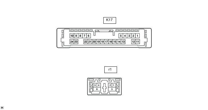
Terminal No. (Symbol) Wiring Color Terminal Description Condition Specified Condition K17-6 (VOI+) - K17-23 (GND) SB - W-B Voice signal Voice guidance sounding A waveform synchronized with sound is output K17-7 (VOI-) - K17-23 (GND) V - W-B Voice signal Voice guidance sounding A waveform synchronized with sound is output K17-8 (SLD1) - Body ground Shielded - Body ground Shield ground Always Below 1 Ω K17-9 (SPD) - K17-23 (GND) BE - W-B Vehicle speed signal See "Check GPS and Vehicle Sensors" in Operation Check
- K17-10 (+B) - K17-23 (GND) GR - W-B Power source (+B) Always 11 to 14 V K17-13 (MIC+) - K17-23 (GND) W - W-B Microphone voice signal See "Microphone Check (MEU)" in Operation Check
- K17-14 (MIC-) - Body ground B - Body ground Microphone voice signal See "Microphone Check (MEU)" in Operation Check
- K17-19 (REV2) - K17-23(GND) W - W-B Reverse signal Engine running, shift position not in R → in R 2 V or less → 11 to 14 V K17-21 (SUP) - K17-23 (GND) B - W-B Power source (ACC) 20 seconds elapse after turning the ignition switch to ACC 11 to 14 V K17-22 (RST)* R - - - K17-23 (GND) - Body ground W-B - Body ground Ground Always Below 1 Ω r1-1 (GVO-) - Video signal (Digital) - - r1-2 (GVO+) - Video signal (Digital) - - r1-3 (GVG1) - Body ground Shielded - Body ground Shield ground Always Below 1 Ω r1-4 (US4+) - USB communication line - - r1-5 (US4-) - USB communication line - - r1-6 (UGD4) - Body ground Shielded - Body ground Shield ground Always Below 1 Ω
-
*: It is connected, but not used
-
-
STEREO COMPONENT AMPLIFIER ASSEMBLY (for 9 Speakers)
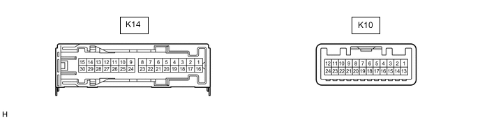
Terminal No. (Symbol) Wiring Color Terminal Description Condition Specified Condition K14-1 (+B) - K14-3 (GND) L - W-B Power source (+B) Always 11 to 14 V K14-3 (GND) - Body ground W-B - Body ground Ground Always Below 1 V K14-8 (WF2+) - K14-3 (GND) W - W-B Sound signal (Woofer) Audio system playing A waveform synchronized with sound signals is output K14-9 (RL+) - K14-3 (GND) B - W-B Sound signal (Rear Left) Audio system playing A waveform synchronized with sound signals is output K14-10 (WF1+) - K14-3 (GND) BE - W-B Sound signal (Woofer) Audio system playing A waveform synchronized with sound signals is output K14-11 (RR+) - K14-3 (GND) R - W-B Sound signal (Rear Right) Audio system playing A waveform synchronized with sound signals is output K14-12 (TWL+) - K14-3 (GND) B - W-B Sound signal (Front Left) Audio system playing A waveform synchronized with sound signals is output K14-13 (FL+) - K14-3 (GND) LG - W-B Sound signal (Front Left) Audio system playing A waveform synchronized with sound signals is output K14-14 (TWR+) - K14-3 (GND) BE - W-B Sound signal (Front Right) Audio system playing A waveform synchronized with sound signals is output K14-15 (FR+) - K14-3 (GND) BE - W-B Sound signal (Front Right) Audio system playing A waveform synchronized with sound signals is output K14-16 (+B2) - K14-3 (GND) B - W-B Power source (+B) Always 11 to 14 V K14-18 (GND2) - Body ground W-B - Body ground Ground Always Below 1 V K14-23 (WF2-) - K14-3 (GND) R - W-B Sound signal (Woofer) Audio system playing A waveform synchronized with sound signals is output K14-24 (RL-) - K14-3 (GND) LG - W-B Sound signal (Rear Left) Audio system playing A waveform synchronized with sound signals is output K14-25 (WF1-) - K14-3 (GND) L - W-B Sound signal (Woofer) Audio system playing A waveform synchronized with sound signals is output K14-26 (RR-) - K14-3 (GND) W - W-B Sound signal (Rear Right) Audio system playing A waveform synchronized with sound signals is output K14-27 (TWL-) - K14-3 (GND) GR - W-B Sound signal (Front Left) Audio system playing A waveform synchronized with sound signals is output K14-28 (FL-) - K14-3 (GND) W - W-B Sound signal (Front Left) Audio system playing A waveform synchronized with sound signals is output K14-29 (TWR-) - K14-3 (GND) L - W-B Sound signal (Front Right) Audio system playing A waveform synchronized with sound signals is output K14-30 (FR-) - K14-3 (GND) L - W-B Sound signal (Front Right) Audio system playing A waveform synchronized with sound signals is output K10-1 (MUTE) - K14-3 (GND) BE - W-B Mute signal Ignition switch ACC
Audio system playing
3.5 V or higher Audio system changing modes Below 1 V K10-2 (L-) - K14-3 (GND) G - W-B Sound signal (Left) Audio system playing A waveform synchronized with sound signals is output K10-3 (L+) - K14-3 (GND) B - W-B Sound signal (Left) Audio system playing A waveform synchronized with sound signals is output K10-4 (R-) - K14-3 (GND) R - W-B Sound signal (Right) Audio system playing A waveform synchronized with sound signals is output K10-5 (R+) - K14-3 (GND) W - W-B Sound signal (Right) Audio system playing A waveform synchronized with sound signals is output K10-6 (SLD) - Body ground Shielded - Body ground Shield ground Always Below 1 V K10-7 (TX-) W AVC-LAN communication signal - - K10-8 (TX+) B AVC-LAN communication signal - - K10-11 (SPD) - K14-3 (GND) G - W-B Vehicle speed signal Ignition switch ON
Wheel being rotated
Pulse generation K10-12 (ACC) - K14-3 (GND) LG - W-B Power source (ACC) Ignition switch off Below 1 V Ignition switch ACC 11 to 14 V K10-14 (II1-) - K14-3 (GND) BR - W-B Voice signal Voice guidance sounding A waveform synchronized with voice signals is output K10-15 (II1+) - K14-3 (GND) Y - W-B Voice signal Voice guidance sounding A waveform synchronized with voice signals is output K10-18 (SLD1) - Body ground Shielded - Body ground Shield ground Always Below 1 V K10-19 (TXD-)* GR AVC-LAN communication signal - - K10-20 (TXD+)* L AVC-LAN communication signal - -
-
*: w/ Cooler Control Switch Assembly
-
-
COOLER CONTROL SWITCH ASSEMBLY (w/ Cooler Control Switch Assembly)

Terminal No.
(Symbol)
Wiring Color Terminal Description Condition Specified Condition Z1-1 (ACC) - Z1-16 (GND) GR - W-B Power source (ACC) Ignition switch off Below 1 V Ignition switch ACC 11 to 14 V Z1-7 (TX+) B AVC-LAN communication signal - - Z1-8 (TX-) W AVC-LAN communication signal - - Z1-9 (+B) - Z1-16 (GND) R - W-B Power source (+B) Always 11 to 14 V Z1-10 (IG+) - Z1-16 (GND) L - W-B Power source (IG) Ignition switch off Below 1 V Ignition switch ON 11 to 14 V Z1-16 (GND) - Body ground W-B - Body ground Ground Always Below 1 V -
COMBINATION METER ASSEMBLY
-
HEADUP DISPLAY (METER MIRROR SUB-ASSEMBLY) (w/ Headup Display System)
-
SKID CONTROL ECU (BRAKE ACTUATOR ASSEMBLY)