STOP AND START SYSTEM(for V35A-FTS) Stop and Start Cancel Switch Circuit
DESCRIPTION
Stop and start control can be disabled by pressing the stop and start system cancel switch (integration control and panel assembly). The stop and start system cancel switch (integration control and panel assembly) is a momentary-type switch that switches between on and off when the switch is pressed. While stop and start control is disabled, the stop and start cancel indicator light is illuminated to inform the driver.
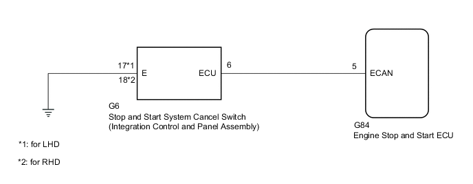
WIRING DIAGRAM
PROCEDURE
-
READ VALUE USING GTS (STOP&START CANCEL SWITCH)
-
Connect the GTS to the DLC3.
-
Turn the engine switch on (IG).
-
Turn the GTS on.
-
Enter the following menus: Powertrain / Stop and Start / Data List / Stop&Start Cancel Switch.
Powertrain > Stop and Start > Data ListTester Display Stop&Start Cancel Switch -
Read the value when the stop and start system cancel switch (integration control and panel assembly) is pressed.
OK Tester Display Condition Normal Condition Stop&Start Cancel Switch Stop and start system cancel switch (Integration control and panel assembly) is pressed ON Stop and start system cancel switch (Integration control and panel assembly) is not pressed OFF Result Proceed to OK NG
OK 
PROCEED TO NEXT SUSPECTED AREA SHOWN IN PROBLEM SYMPTOMS TABLE Click here
NG 
-
-
INSPECT STOP AND START SYSTEM CANCEL SWITCH (INTEGRATION CONTROL AND PANEL ASSEMBLY)
-
Inspect the stop and star system cancel switch (integration control and panel assembly).
Result Proceed to OK NG
NG
REPLACE INTEGRATION CONTROL & PANEL ASSEMBLY Click here
OK
-
-
CHECK HARNESS AND CONNECTOR (STOP AND START SYSTEM CANCEL SWITCH (INTEGRATION CONTROL AND PANEL ASSEMBLY) - BODY GROUND)
-
Disconnect the G6 stop and start system cancel switch (integration control and panel assembly) connector.
-
Measure the resistance according to the value(s) in the table below.
Standard Resistance Tester Connection Condition Specified Condition G6-17 (E)*1 - Body ground Always Below 1 Ω G6-18 (E)*2 - Body ground Always Below 1 Ω
-
*1: for LHD
-
*2: for RHD
Result Proceed to OK NG -
NG
REPAIR OR REPLACE HARNESS OR CONNECTOR
OK
-
-
CHECK HARNESS AND CONNECTOR (ENGINE STOP AND START ECU - STOP AND START SYSTEM CANCEL SWITCH (INTEGRATION CONTROL AND PANEL ASSEMBLY))
-
Disconnect the G84 engine stop and start ECU connector.
-
Disconnect the G6 stop and start system cancel switch (integration control and panel assembly) connector.
-
Measure the resistance according to the value(s) in the table below.
Standard Resistance Tester Connection Condition Specified Condition G84-5 (ECAN) - G6-6 (ECU) Always Below 1 Ω G84-5 (ECAN) - Body ground Always 10 kΩ or higher G6-6 (ECU) - Body ground Always 10 kΩ or higher Result Proceed to OK NG
OK
PROCEED TO NEXT SUSPECTED AREA SHOWN IN PROBLEM SYMPTOMS TABLE Click here
NG
REPAIR OR REPLACE HARNESS OR CONNECTOR
-