IGNITION SWITCH INSPECTION
PROCEDURE
INSPECT IGNITION OR STARTER SWITCH ASSEMBLY
-
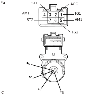
*a
Component without harness connected
(Ignition or Starter Switch Assembly)
*b
LOCK
*c
ACC
*d
ON
*e
START
Check the resistance.
Measure the resistance according to the value(s) in the table below.
Standard Resistance
Tester Connection
Switch Condition
Specified Condition
Between all terminals
LOCK
1 MΩ or higher
4 (AM1) - 2 (ACC)
ACC
Below 1 Ω
4 (AM1) - 2 (ACC) - 1 (IG1)
ON
Below 1 Ω
6 (IG2) - 5 (AM2)
4 (AM1) - 3 (ST1) - 1 (IG1)
START
Below 1 Ω
7 (ST2) - 6 (IG2) - 5 (AM2)
If the result is not as specified, replace the ignition or starter switch assembly.
-