CYLINDER BLOCK DISASSEMBLY
PROCEDURE
REMOVE OIL JET
-
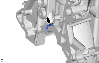
Remove the oil jet from the cylinder block sub-assembly.
-
REMOVE PISTON SUB-ASSEMBLY WITH CONNECTING ROD SUB-ASSEMBLY
Note:Do not turn the crankshaft.
-
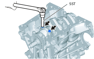
Using SST, remove the 2 connecting rod bolts.
09205-16011
Note:Arrange the removed parts for each cylinder in the correct order.
-
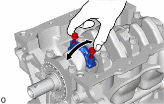
Using the 2 removed connecting rod bolts, remove the connecting rod bearing cap and connecting rod bearing by wiggling the connecting rod bearing cap back and forth.
Push the piston, connecting rod sub-assembly and connecting rod bearing through the top of the cylinder block sub-assembly.
Tip:Keep the piston, connecting rod sub-assembly and connecting rod bearing cap together.
Arrange the piston and connecting rod sub-assembly for each cylinder in the correct order.
-
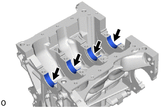
REMOVE CONNECTING ROD BEARING
-
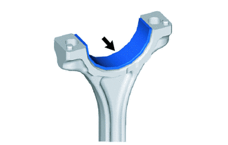
Remove the connecting rod bearing from the connecting rod sub-assembly.
Tip:Arrange the removed parts in the correct order.
-
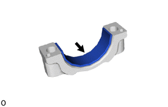
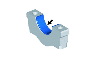
Remove the connecting rod bearing from the connecting rod bearing cap.
Tip:Arrange the removed parts in the correct order.
-
REMOVE PISTON RING SET
-
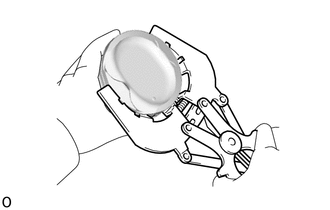
Using a piston ring expander, remove the No. 1 compression ring and No. 2 compression ring.
Remove the expander spacer and 2 side rails by hand.
-
REMOVE PISTON (w/ Pin)
-
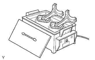
Gradually heat each piston to approximately 80 to 90°C (176 to 194°F).
Using SST, press the piston pin out of the piston, and remove the piston.
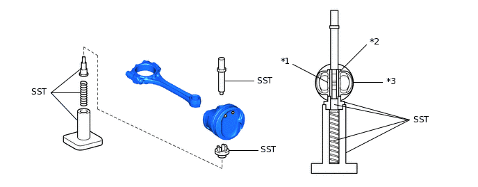
*1
Connecting Rod Sub-assembly
*2
Piston Pin
*3
Piston
-
-
09221-25026
09221-00021
09221-00030
09221-00130
09221-00141
09221-00150
Tip:The piston and piston pin are a matched set.
Arrange the pistons, piston pins, connecting rod sub-assemblies and connecting rod bearings in the correct order.
-
REMOVE CRANKSHAFT
-
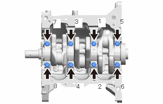
Remove the 8 crankshaft bearing cap set bolts in the order shown in the illustration.
Note:Loosen the crankshaft bearing cap set bolts in 2 or 3 steps in the order shown in the illustration.
-
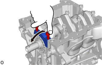
Remove the 4 crankshaft bearing caps and 4 crankshaft bearings from the cylinder block sub-assembly.
Note:Arrange the removed parts in the correct order.
Tip:If it is difficult to remove the crankshaft bearing cap, lightly tap it with a hammer.
Move the top of the crankshaft bearing cap back and forth in the axial direction.
-
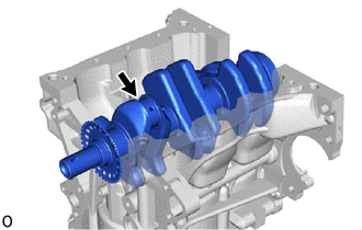
Remove the crankshaft from the cylinder block sub-assembly.
-
REMOVE CRANKSHAFT THRUST WASHER UPPER
-
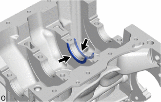
Remove the 2 crankshaft thrust washer uppers from the No. 3 journal position of the cylinder block sub-assembly.
-
REMOVE CRANKSHAFT BEARING
-
Remove the 4 crankshaft bearings from the cylinder block sub-assembly.
Tip:Arrange the removed parts in the correct order.
-
Remove the 4 crankshaft bearings from the 4 crankshaft bearing caps.
Tip:Arrange the removed parts in the correct order.
-
REMOVE NO. 1 OIL NOZZLE SUB-ASSEMBLY
-
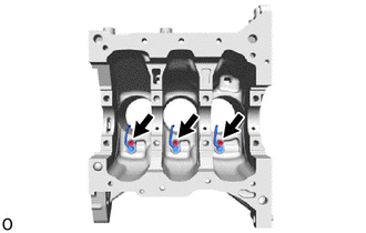
Using a 5 mm hexagon socket wrench, remove the 3 bolts and 3 No. 1 oil nozzle sub-assemblies.
-