BLIND SPOT MONITOR SYSTEM TERMINALS OF ECU
-
*1: for LHD
*2: for RHD
BLIND SPOT MONITOR SENSOR LH (MASTER)

Terminal No. (Symbol)
Wiring Color
Terminal Description
Condition
Specified Condition
R1-3 (BIND) - R1-10 (BLGD)
B - W-B
Blind spot monitor indicator power source signal
Ignition switch ON, blind spot monitor main switch (warning cancel switch assembly*1 or telltale light assembly*2) on
11 to 14 V
Ignition switch ON, blind spot monitor main switch (warning cancel switch assembly*1 or telltale light assembly*2) off
Below 1 V
R1-4 (OMIL) - R1-10 (BLGD)
V - W-B
Outer rear view mirror indicator power source signal LH
Outer rear view mirror indicator illuminated
2.5 to 7.5 V
Outer rear view mirror indicator not illuminated
Below 1 V
R1-5 (BLB) - R1-10 (BLGD)
L - W-B
IG power source signal
Ignition switch off
Below 1 V
Ignition switch ON
11 to 14 V
R1-8 (BSSW) - R1-10 (BLGD)
W - W-B
Blind spot monitor main switch (warning canceling switch assembly*1 or telltale light assembly*2) power source signal
Ignition switch ON, blind spot monitor main switch (warning cancel switch assembly*1 or telltale light assembly*2) on
11 to 14 V
Ignition switch ON, blind spot monitor main switch (warning cancel switch assembly*1 or telltale light assembly*2) off
Below 1 V
R1-10 (BLGD) - Body ground
W-B - Body ground
Ground
Always
Below 1 V
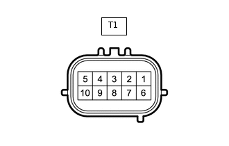
BLIND SPOT MONITOR SENSOR RH (SLAVE)
Terminal No. (Symbol)
Wiring Color
Terminal Description
Condition
Specified Condition
T1-4 (OMIR) - T1-10 (BRGB)
V - W-B
Outer rear view mirror indicator power source signal RH
Outer rear view mirror indicator illuminated
2.5 to 7.5 V
Outer rear view mirror indicator not illuminated
Below 1 V
T1-5 (BRB) - T1-10 (BRGB)
L - W-B
IG power source signal
Ignition switch off
Below 1 V
Ignition switch ON
11 to 14 V
T1-10 (BRGB) - Body ground
W-B - Body ground
Ground
Always
Below 1 V