PARKING BRAKE PEDAL(for RHD) INSTALLATION

PROCEDURE
-
INSTALL PARKING BRAKE CONTROL PEDAL ASSEMBLY
-
Install the parking brake control pedal assembly with the 2 bolts and nut.
- Torque:
- 15 N*m { 148 kgf*cm, 11 ft.*lbf }
-
Connect the parking brake switch connector.
-
Engage the wire harness clamp.
-
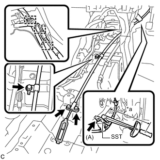
Text in Illustration *a Fulcrum Length Using SST, install the bolt (A).
- SST
- 09961-00950
- Torque:
- without SST
- 15 N*m { 148 kgf*cm, 11 ft.*lbf }
- with SST
- 9.4 N*m { 96 kgf*cm, 83 in.*lbf }
Note
-
Use a torque wrench with a fulcrum length of 250 mm (9.84 in.).
-
This torque value is effective when SST is parallel to the torque wrench.
-
Install the No. 1 parking brake cable assembly with the 3 bolts.
- Torque:
- 15 N*m { 148 kgf*cm, 11 ft.*lbf }
-
Install the No. 1 parking brake cable assembly to the clamp.
-
Engage the 2 wire harness clamps.
-
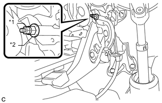
Text in Illustration *1 Lock Nut *2 Adjusting Nut Temporarily install the lock nut.
Tech Tips
After adjusting parking brake pedal travel, tighten the lock nut.
-
-
CONNECT NO. 1 PARKING BRAKE PULL ROD SUB-ASSEMBLY
-
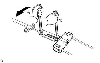
Text in Illustration *a Turn *b Hold Connect the No. 1 parking brake pull rod sub-assembly to the parking brake control pedal assembly as shown in the illustration.
- Torque:
- 5.4 N*m { 55 kgf*cm, 48 in.*lbf }
-
-
INSTALL NO. 1 AIR DUCT SUB-ASSEMBLY
-
INSTALL LOWER NO. 1 INSTRUMENT PANEL AIRBAG ASSEMBLY
Tech Tips
Use the same procedure as for LHD Click here.
-
INSTALL NO. 1 INSTRUMENT PANEL UNDER COVER SUB-ASSEMBLY
Tech Tips
Use the same procedure as for LHD Click here.
-
INSTALL LOWER INSTRUMENT PANEL FINISH PANEL SUB-ASSEMBLY
Tech Tips
Use the same procedure as for LHD Click here.
-
INSTALL GLOVE COMPARTMENT DOOR ASSEMBLY
Tech Tips
Use the same procedure as for LHD Click here.
-
INSTALL INSTRUMENT PANEL BOX ASSEMBLY
Tech Tips
Use the same procedure as for LHD Click here.
-
INSTALL LOWER INSTRUMENT PANEL FINISH PANEL ASSEMBLY
Tech Tips
Use the same procedure as for LHD Click here.
-
INSTALL UPPER INSTRUMENT PANEL FINISH PANEL
Tech Tips
Use the same procedure as for LHD Click here.
-
INSTALL INTEGRATION CONTROL AND PANEL
Tech Tips
Use the same procedure as for LHD Click here.
-
INSTALL NO. 2 HYBRID BATTERY INTAKE DUCT
-
Engage the 2 guides.
-
Install the No. 2 hybrid battery intake duct with the 2 clips.
-
Install the front floor carpet.
-
-
INSTALL REAR NO. 1 HEATER REGISTER BEZEL
-
Install the rear No.1 heater register bezel with the 2 clips.
-
-
INSTALL FUEL LID LOCK OPEN LEVER SUB-ASSEMBLY
-
INSTALL CENTER PILLAR LOWER GARNISH RH
Tech Tips
Use the same procedure as for the LH side Click here.
-
CONNECT FRONT SEAT OUTER BELT ASSEMBLY RH
Tech Tips
Use the same procedure as for the LH side Click here.
-
INSTALL LAP BELT OUTER ANCHOR COVER (for RH Side)
Tech Tips
Use the same procedure as for the LH side Click here.
-
INSTALL REAR DOOR OPENING TRIM WEATHERSTRIP RH
-
INSTALL REAR DOOR SCUFF PLATE RH
Tech Tips
Use the same procedure as for the LH side Click here.
-
INSTALL FRONT DOOR OPENING TRIM WEATHERSTRIP RH
-
INSTALL COWL SIDE TRIM SUB-ASSEMBLY RH
Tech Tips
Use the same procedure as for the LH side Click here.
-
INSTALL FRONT DOOR SCUFF PLATE RH
Tech Tips
Use the same procedure as for the LH side Click here.
-
INSTALL YAW RATE AND ACCELERATION SENSOR
-
ADJUST PARKING BRAKE PEDAL TRAVEL
-
INSPECT BRAKE WARNING LIGHT