MANUAL TRANSAXLE ASSEMBLY INSTALLATION
CAUTION / NOTICE / HINT
When the transaxle is removed, be sure to use a new clutch release with bearing cylinder and new installation bolts. Removal of the transaxle allows the compressed clutch release with bearing cylinder to return to its original position, and dust could damage the seal of the clutch release with bearing cylinder, possibly causing clutch fluid leaks.
PROCEDURE
INSTALL WIRE HARNESS CLAMP BRACKET
-
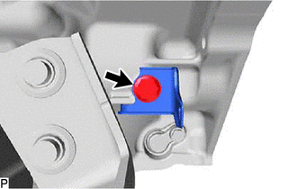
for Rear of Vehicle (w/ Stop and Start System):
Install the wire harness clamp bracket with the bolt.
19.1 N*m
195 kgf*cm
14 ft.*lbf
-
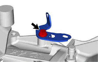
for Front of Vehicle:
Install the wire harness clamp bracket with the bolt.
19.1 N*m
195 kgf*cm
14 ft.*lbf
-
INSTALL TRANSFER AND TRANSAXLE SETTING STUD BOLT
Transfer Side:
Clean the transfer and transaxle setting stud bolt holes.
Apply adhesive 1324 to 2 or 3 threads on one half of a new transfer and transaxle setting stud bolt A as shown in the illustration.
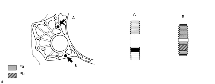
*a
Toyota Genuine Adhesive 1324
*b
Sealant
Adhesive
Toyota Genuine Adhesive 1324, Three Bond 1324 or equivalent
Note:Do not apply adhesive 1324 to the ends of the transfer and transaxle setting stud bolt.
Install the transfer and transaxle setting stud bolt immediately after applying adhesive to prevent the adherence of foreign matter.
Install the 2 new transfer and transaxle setting stud bolts to the transaxle case positions shown in the illustration.
39.2 N*m
400 kgf*cm
29 ft.*lbf
Note:Install the transfer and transaxle setting stud bolt so that the side that has sealant and adhesive is facing the automatic transaxle assembly.
Tip:Stud transfer and transaxle setting stud bolt length:
Stud transfer and transaxle setting stud bolt A: 69 mm (2.72 in.)
Stud transfer and transaxle setting stud bolt B: 47 mm (1.85 in.)
INSTALL TRANSFER ASSEMBLY
INSTALL SPEEDOMETER DRIVEN HOLE COVER SUB-ASSEMBLY
Coat a new O-ring with gear oil.
Install the O-ring to the speedometer driven hole cover sub-assembly.
Install the speedometer driven hole cover sub-assembly to the manual transaxle case with the bolt.
5.5 N*m
56 kgf*cm
49 in.*lbf
INSTALL CLUTCH RELEASE WITH BEARING CYLINDER ASSEMBLY
REMOVE CLUTCH RELEASE BLEEDER SUB-ASSEMBLY
INSPECT CLUTCH PIPE LINE
INSTALL CLUTCH RELEASE BLEEDER SUB-ASSEMBLY
INSTALL CLUTCH ACCUMULATOR ASSEMBLY
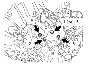
INSTALL REAR ENGINE MOUNTING BRACKET
*a
Temporarily
Temporarily install the rear engine mounting bracket with the 4 bolts.
Tighten the 4 bolts of the rear engine mounting bracket in the order shown in the illustration.
45 N*m
459 kgf*cm
33 ft.*lbf
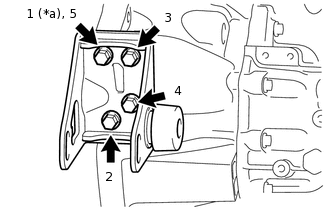
INSTALL ENGINE MOUNTING BRACKET LH
*a
Temporarily
Clean the bolts and the installation holes in the engine mounting bracket LH.
Apply adhesive to the 4 bolts.
Adhesive
Toyota Genuine Adhesive 1324, Three Bond 1324 or equivalent
Temporarily install the engine mounting bracket LH with the 4 bolts.
Tighten the 4 bolts of the engine mounting bracket LH in the order shown in the illustration.
64 N*m
653 kgf*cm
47 ft.*lbf
INSTALL FRONT ENGINE MOUNTING BRACKET
*a
Temporarily
Temporarily install the front engine mounting bracket with the 4 bolts.
Tighten the 4 bolts of the front engine mounting bracket in the order shown in the illustration.
64 N*m
653 kgf*cm
47 ft.*lbf
INSTALL MANUAL TRANSAXLE ASSEMBLY
Align the input shaft with the clutch disc and install the manual transaxle to the engine.
Note:Make sure that the dowel pins are not loose, bent, damaged or scratched and then install the transaxle onto the engine with the contact surfaces of the engine and transaxle flat against each other.
Insert the dowel pins into the dowel holes securely so that the end face of the transaxle assembly fits close against the engine assembly before tightening the bolts.
-
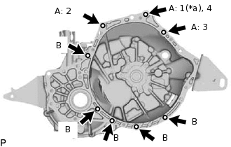
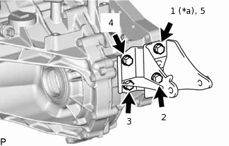
*a
Temporarily
Temporarily install the manual transaxle assembly with the bolt (*a).
Tighten the 3 bolts labeled A in the order shown in the illustration, and then install the 5 bolts labeled B.
for Bolt A
38 N*m
387 kgf*cm
28 ft.*lbf
for Bolt B
40 N*m
408 kgf*cm
30 ft.*lbf
-
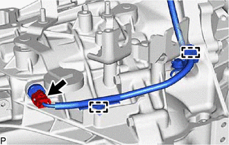
Connect the engine wire.
w/ Stop and Start System:
Connect the neutral position switch connector and 2 clamps.
-
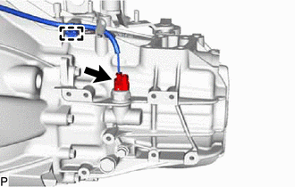
Connect the clamp and back-up light switch connector.
INSTALL STARTER ASSEMBLY (for 3ZR-FE)
for 1.0 kW Type:
for 1.3 kW Type:
INSTALL STARTER ASSEMBLY (for 3ZR-FAE)
INSTALL ENGINE ASSEMBLY WITH TRANSAXLE
for 3ZR-FE:
for 3ZR-FAE: