AUTOMATIC TRANSMISSION UNIT(for V35A-FTS) DISASSEMBLY

PROCEDURE
-
SECURE AUTOMATIC TRANSMISSION ASSEMBLY
-
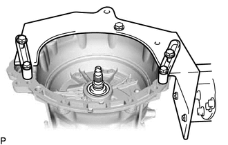
Install the automatic transmission assembly to an overhaul attachment.
-
-
REMOVE NO. 1 BREATHER PLUG (ATM)
-
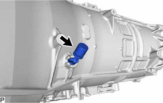
Remove the No. 1 breather plug (ATM) from the automatic transmission case.
-
-
REMOVE SHIFT CONTROL ACTUATOR ASSEMBLY
-
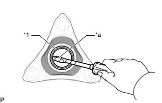
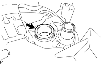
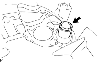
REMOVE OIL COOLER TUBE UNION
-
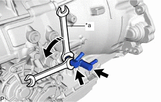
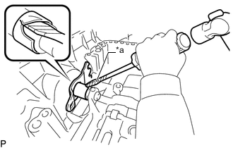
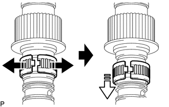
*a Hold 
Turn Remove the 2 oil cooler tube unions from the automatic transmission case.
-
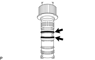
Remove the 2 O-rings from the 2 oil cooler tube unions
-
-
REMOVE TRANSMISSION CASE ADAPTER
-
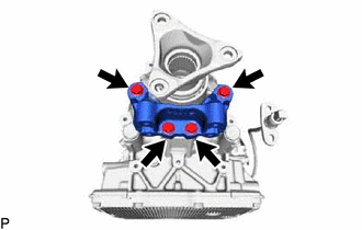
Remove the 4 bolts and transmission case adapter from the automatic transmission case.
-
-
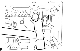
REMOVE AUTOMATIC TRANSMISSION FLANGE YOKE ASSEMBLY
-
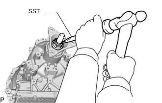
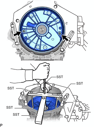
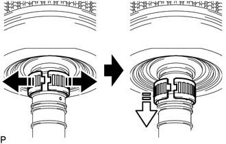
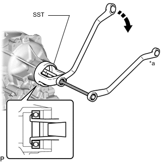
Using SST and a hammer, release the staked part of the lock nut.
- SST
- 09930-00010
Note
-
Use SST with the tapered part facing the shaft.
-
Do not modify the tip of SST with a grinder or other device.
-
Completely release the staked part of the lock nut before removing it.
-
Do not damage the threads of the output shaft assembly.
-
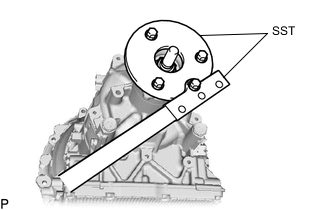
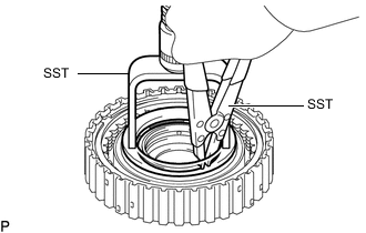
Using SST, secure the automatic transmission flange yoke assembly.
- SST
- 09330-00021
- 09950-30012 ( 09955-03040 )
Tech Tips
Use an M8 x 1.25 bolt with an under head length of 45 mm (1.77 in.) to secure bolt.
-
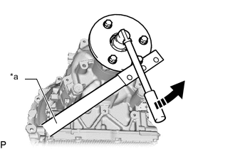
*a Hold Turn Using a 30 mm deep socket wrench, remove the lock nut from the automatic transmission flange yoke assembly.
-
Tap the automatic transmission flange yoke assembly with a plastic-faced hammer to remove it.
-
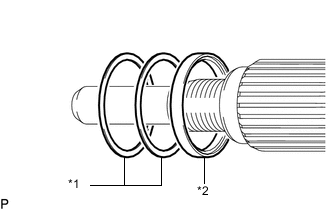
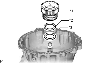
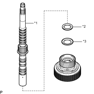
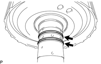
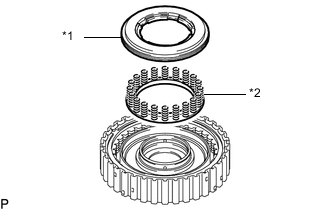
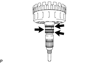
*1 Spacer *2 Rear Cover Sleeve Remove the 2 spacers and rear cover sleeve from the output shaft assembly.
-
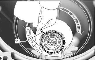
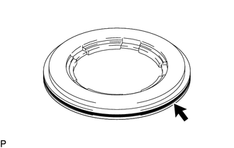
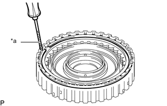
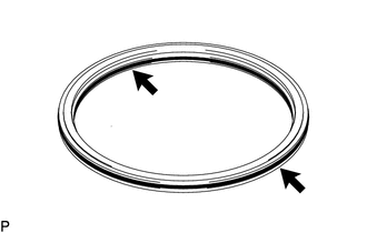
*1 Flange Yoke Type V Oil Seal *a Protective Tape Using a screwdriver with its tip wrapped with protective tape, remove the flange yoke type V oil seal from the automatic transmission flange yoke assembly.
Note
When removing the flange yoke type V oil seal, make sure not to damage the automatic transmission flange yoke assembly.
Tech Tips
Tape the screwdriver tip before use.
-
-
REMOVE AUTOMATIC TRANSMISSION OIL PAN SUB-ASSEMBLY
-
Remove the refill plug and gasket from the automatic transmission case.
-
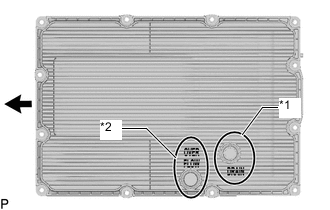
*1 Drain Plug *2 Overflow Plug 
Front of Vehicle Using a 6 mm hexagon socket wrench, remove the overflow plug from the automatic transmission oil pan sub-assembly.
-
Using a 6 mm hexagon socket wrench, remove the drain plug from the automatic transmission oil pan sub-assembly.
-
Remove the O-ring from the drain plug.
-
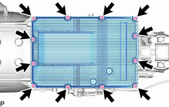
Remove the 12 bolts and automatic transmission oil pan sub-assembly.
Note
Transmission fluid is left in the automatic transmission oil pan sub-assembly. Therefore, remove it parallel to the ground so that the fluid does not spill.
-
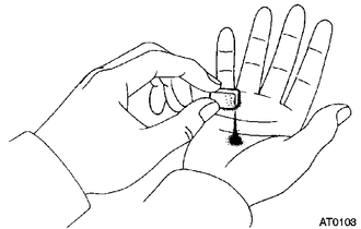
Examine the particles in the automatic transmission oil pan sub-assembly.
-
Use the removed oil pan magnets to collect any steel chips.
Examine the chips and particles in the automatic transmission oil pan sub-assembly and on the oil pan magnets to determine what type of wear might be found in the automatic transmission assembly.
Result Steel (magnetic): Bearing, gear and clutch plate wear Brass (non-magnetic): Bushing wear
-
-
-
REMOVE NO. 1 TRANSMISSION OIL FILLER TUBE
-
REMOVE ACCUMILATOR WITH SOLENOID ASSEMBLY (w/ Stop And Start System)
-
REMOVE TRANSMISSION OIL PIPE (w/ Stop And Start System)
-
REMOVE TRANSMISSION VALVE BODY ASSEMBLY
-
REMOVE TRANSMISSION REVOLUTION SENSOR (NT)
-
REMOVE TRANSMISSION REVOLUTION SENSOR (SP2)
-
REMOVE TRANSMISSION WIRE
-
REMOVE OIL PUMP SUCTION PIPE
-
Remove the oil pump suction pipe from the front oil pump assembly.
-
Remove the O-ring from the oil pump suction pipe.
-
-
REMOVE OIL PUMP DELIVERY PIPE
-
Remove the oil pump delivery pipe from the front oil pump assembly.
-
Remove the O-ring from the oil pump delivery pipe.
-
-
REMOVE BRAKE DRUM GASKET
-

Remove the 3 brake drum gaskets from the automatic transmission case.
-
-
REMOVE PARKING LOCK PAWL BRACKET
-
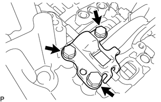
Remove the 3 bolts and parking lock pawl bracket from the automatic transmission case.
-
-
REMOVE PARKING LOCK ROD SUB-ASSEMBLY
-
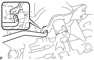
*1 Manual Valve Lever Sub-assembly *2 Parking Lock Rod Sub-assembly Remove the parking lock rod sub-assembly from the manual valve lever sub-assembly.
-
-
REMOVE PARKING LOCK PAWL SHAFT
-
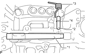
*1 Parking Lock Pawl *2 Parking Lock Pawl Shaft *3 Spring *4 E-ring Remove the parking lock pawl shaft, parking lock pawl and spring from the automatic transmission case.
-
Remove the E-ring from the parking lock pawl shaft.
-
-
REMOVE MANUAL VALVE LEVER SUB-ASSEMBLY
-
*a Protective Tape Using a screwdriver and a hammer, cut off the spacer and remove it from the manual valve lever shaft.
Note
Be careful not to damage the manual valve lever shaft.
Tech Tips
Tape the screwdriver tip before use.
-
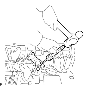
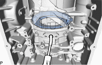
Using a 5 mm pin punch and hammer, remove the spring pin from the manual valve lever shaft.
Tech Tips
Slowly tap out the spring pin so that it does not fall into the automatic transmission case.
-
Remove the manual valve lever shaft and manual valve lever sub-assembly from the automatic transmission case.
-
-
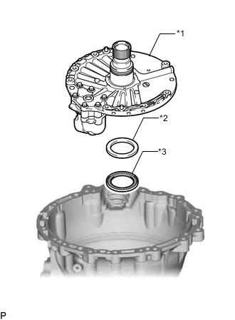
REMOVE FRONT OIL PUMP COVER SUB-ASSEMBLY
-

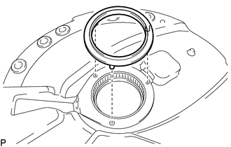
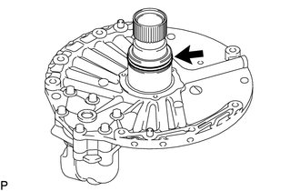
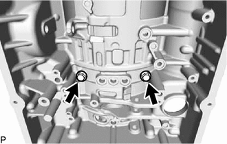
Remove the 8 bolts from the front oil pump cover sub-assembly.
-
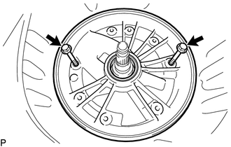
Temporarily install the 2 bolts to the position shown in the illustration and remove the front oil pump cover sub-assembly.
Tech Tips
Use an M10 x 1.25 bolt.
-
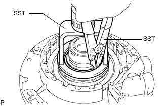
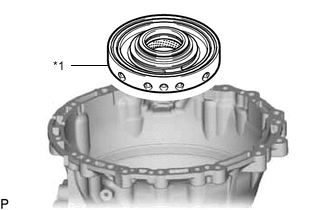
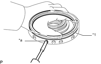
SST bolt installation position If the front oil pump cover sub-assembly is stuck and cannot be detached:
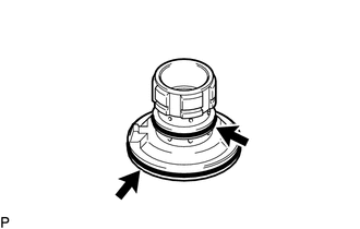
Using SST, rotate and remove the front oil pump cover sub-assembly by hand as shown in the illustration.
- SST
- 09380-60012 ( 09381-06010, 09381-06050, 09381-06120 )
- 09950-50013 ( 09955-05010 )
- 09322-35010 ( 09322-03030 )
-
Remove the O-ring from the front oil pump cover sub-assembly.
-
Remove the gear thrust washer from the front oil pump cover sub-assembly.
-
-
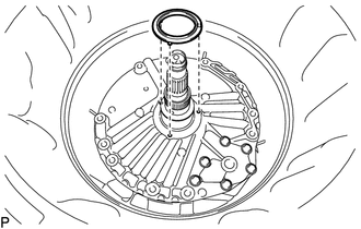
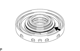
REMOVE FRONT OIL PUMP OIL SEAL
-
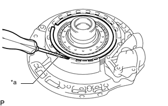
*a Protective Tape Using a screwdriver, remove the front oil pump oil seal from the front oil pump cover sub-assembly.
Note
Be careful not to damage the front oil pump cover sub-assembly.
Tech Tips
Tape the screwdriver tip before use.
-
-
REMOVE OIL PUMP DRIVE SHAFT SUB-ASSEMBLY WITH DRIVE SPROCKET AND TRANSMISSION DRIVE CHAIN
-
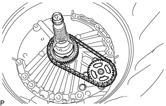
Remove the oil pump drive shaft sub-assembly with drive sprocket and transmission drive chain from the front oil pump assembly.
-
Remove the oil pump drive shaft sub-assembly and drive sprocket from the transmission drive chain.
-
-
INSPECT TRANSMISSION DRIVE CHAIN
-
INSPECT OIL PUMP DRIVE SHAFT SUB-ASSEMBLY
-
INSPECT DRIVE SPROCKET
-
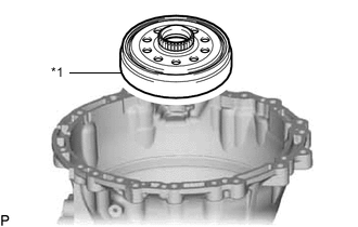
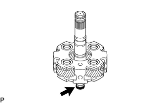
REMOVE FRONT OIL PUMP ASSEMBLY
-
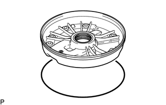
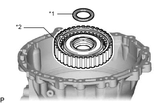
Remove the gear thrust washer from the front oil pump assembly.
-
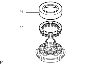
*1 Front Oil Pump Assembly *2 Thrust Bearing Race *3 Thrust Needle Roller Bearing Remove the front oil pump assembly, thrust needle roller bearing and thrust bearing race.
Note
Be careful not to damage the front oil pump assembly.
Tech Tips
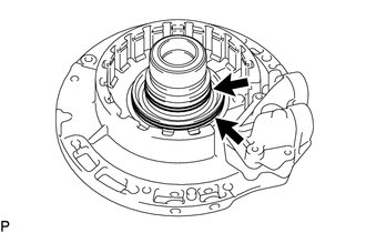
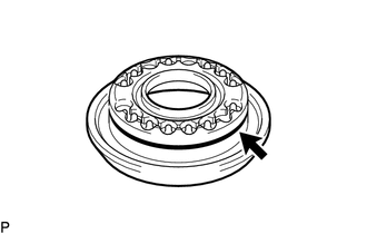
When the front oil pump assembly cannot be detached:Using a plastic-faced hammer and lightly tap the area shown in the illustration until the front oil pump assembly has slightly lifted and then remove it
-
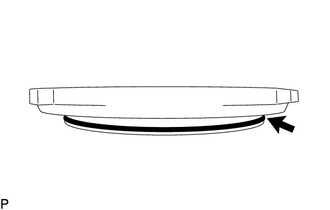
Remove the oil seal ring from the front oil pump assembly.
-
-
INSPECT FRONT OIL PUMP ASSEMBLY
-
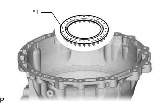
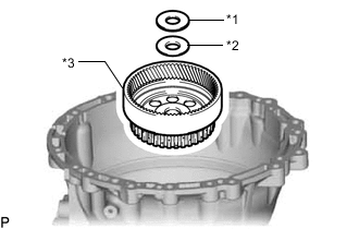
REMOVE NO. 1 BRAKE DISC
-
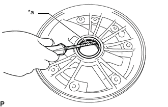
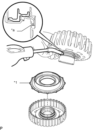
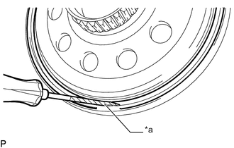
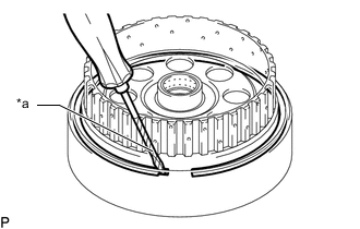
*a Protective Tape Using a screwdriver, remove the snap ring from the front oil pump assembly.
Note
Be careful not to damage the front oil pump assembly.
Tech Tips
Tape the screwdriver tip before use.
-
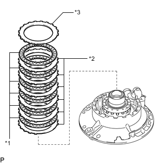
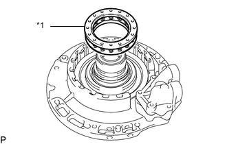
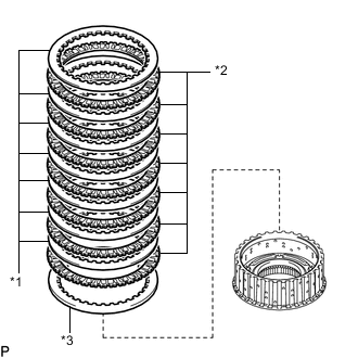
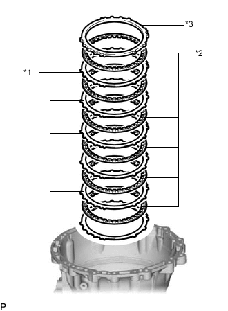
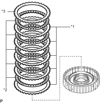
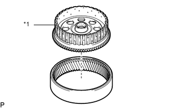
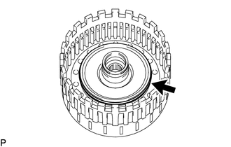
*1 No. 1 Brake Disc *2 No. 1 Brake Plate *3 No. 1 Brake Flange Remove the 6 No. 1 brake plates, 6 No. 1 brake discs and No. 1 brake flange from the front oil pump assembly.
-
-
INSPECT NO. 1 BRAKE DISC
-
REMOVE NO. 1 BRAKE PISTON
-
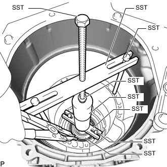
Set SST on the 2nd brake return with retainer spring sub-assembly, and compress the 2nd brake return with retainer spring sub-assembly using a press.
- SST
- 09320-89010
-
Using SST, remove the snap ring from the front oil pump assembly.
- SST
- 09350-30020 ( 09350-07070 )
-
*1 2nd Brake Return with Retainer Spring Sub-assembly Remove the 2nd brake return with retainer spring sub-assembly from the front oil pump assembly.
-
While holding the No. 1 brake piston, apply compressed air to the oil hole of the front oil pump assembly to remove the No. 1 brake piston from the front oil pump assembly.
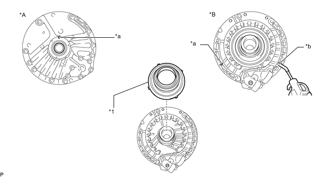
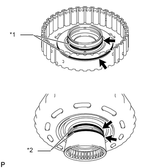
*A Front Side *B Rear Side *1 No. 1 Brake Piston - - *a Cover the oil hole *b Blow air into the oil hole -
Remove the 2 O-rings from the front oil pump assembly.
-
-
INSPECT 2ND BRAKE RETURN WITH RETAINER SPRING SUB-ASSEMBLY
-
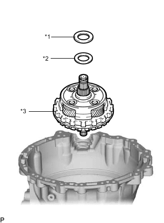
REMOVE FRONT PLANETARY SUN GEAR SUB-ASSEMBLY
-
*1 Front Planetary Sun Gear Sub-assembly *2 Thrust Needle Roller Bearing *3 Thrust Bearing Race Remove the front planetary sun gear sub-assembly, thrust needle roller bearing and thrust bearing race.
-
-
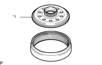
REMOVE FRONT PLANETARY GEAR ASSEMBLY
-
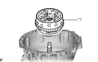
*1 Front Planetary Gear Assembly Remove the front planetary gear assembly from the C-2 clutch assembly.
-
-
INSPECT FRONT PLANETARY GEAR ASSEMBLY
-
REMOVE C-2 CLUTCH ASSEMBLY
-
*1 C-2 Clutch Assembly *2 Thrust Bearing Race *3 Thrust Needle Roller Bearing Remove the C-2 clutch assembly, thrust needle roller bearing and thrust bearing race.
-
Remove the 9 oil seal rings from the C-2 clutch assembly.
-
-
REMOVE INPUT SHAFT SUB-ASSEMBLY
-
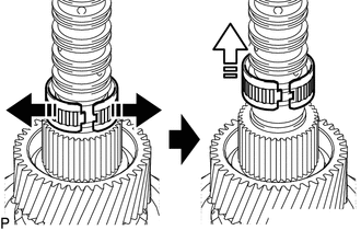
Expand the opening of the bearing 
Remove in this direction Remove the input shaft front thrust bearing from the input shaft sub-assembly as shown in the illustration.
-
Expand the opening of the bearing Remove in this direction Remove the direct disc clutch thrust needle roller bearing from the input shaft sub-assembly as shown in the illustration.
-
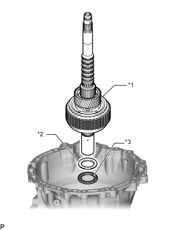
*1 Input Shaft Sub-assembly *2 Thrust Needle Roller Bearing *3 Thrust Bearing Race Remove the input shaft sub-assembly, thrust needle roller bearing and thrust bearing race from the planetary sun gear.
-
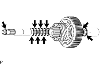
Remove the 2 oil seal rings from the input shaft sub-assembly.
-
Expand the opening of the bearing Remove in this direction Remove the direct disc clutch thrust needle roller bearing from the input shaft sub-assembly as shown in the illustration.
-
-
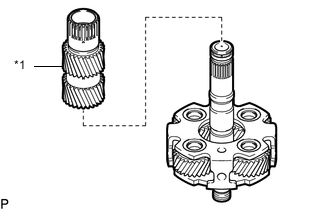
REMOVE PLANETARY SUN GEAR
-
*1 Planetary Sun Gear Remove the planetary sun gear from the C-2 clutch drum sub-assembly.
-
-
REMOVE NO. 2 CLUTCH DISC
-
Set SST on the No. 2 transmission clutch hub, and compress the direct clutch return spring sub-assembly (C-2 clutch) using a press.
- SST
- 09950-60011 ( 09951-00550 )
- 09350-32014 ( 09351-32040 )
-
Using SST, remove the snap ring from the C-2 clutch reaction sleeve sub-assembly.
- SST
- 09350-30020 ( 09350-07070 )
-
*1 C-2 Clutch Drum Sub-assembly Remove the C-2 clutch drum sub-assembly from the C-2 clutch piston sub-assembly.
-
*1 No. 2 Clutch Hub Thrust Washer Remove the No. 2 clutch hub thrust washer from the C-2 clutch drum sub-assembly.
-
*1 No. 2 Clutch Plate *2 No. 2 Clutch Disc *3 No. 2 Clutch Flange Remove the 7 No. 2 clutch plates, 7 No. 2 clutch discs and No. 2 clutch flange from the No. 2 transmission clutch hub.
-
-
INSPECT NO. 2 CLUTCH DISC
-
REMOVE C-2 CLUTCH PISTON
-
*1 No. 2 Clutch Balancer *2 Direct Clutch Return Spring Sub-assembly (C-2 clutch) Remove the No. 2 clutch balancer and direct clutch return spring sub-assembly (C-2 clutch) from the C-2 clutch piston.
-

*1 C-2 Clutch Piston *2 C-2 Clutch Reaction Sleeve Sub-assembly Remove the C-2 clutch piston from the C-2 clutch reaction sleeve sub-assembly.
-
Remove the O-ring from the C-2 clutch piston.
-
Remove the 2 O-rings from the C-2 clutch reaction sleeve sub-assembly.
-
-
INSPECT DIRECT CLUTCH RETURN SPRING SUB-ASSEMBLY (C-2 CLUTCH)
-
REMOVE FRONT PLANETARY RING GEAR WITH C-1 CLUTCH ASSEMBLY
-
*1 Front Planetary Ring Gear with C-1 Clutch Assembly *2 Thrust Bearing Race Remove the front planetary ring gear with C-1 clutch assembly and thrust bearing race.
-
-
REMOVE FRONT PLANETARY RING GEAR
-
*a Protective Tape Using a screwdriver, remove the snap ring from the C-1 clutch assembly.
Note
Be careful not to damage the C-1 clutch assembly.
Tech Tips
Tape the screwdriver tip before use.
-
*1 Front Planetary Ring Gear Remove the front planetary ring gear from the C-1 clutch assembly.
-
-
REMOVE C-2 DRUM SUB-ASSEMBLY
Note
Do not disassemble the C-1 clutch assembly.
If disassembled, replace the C-1 clutch assembly with a new one.
-
*1 C-2 Drum Sub-assembly *2 Thrust Needle Roller Bearing *3 Thrust Bearing Race *4 C-1 Clutch Assembly Remove the C-2 drum sub-assembly, thrust needle roller bearing and thrust bearing race from the C-1 clutch assembly.
-
Remove the 2 oil seal rings from the C-2 drum sub-assembly.
-
-
INSPECT C-1 CLUTCH ASSY
-
REMOVE NO. 2 BRAKE DISC
-
*a Protective Tape Using a screwdriver, remove the snap ring from the automatic transmission case.
Note
Be careful not to damage the automatic transmission case.
Tech Tips
Tape the screwdriver tip before use.
-
*1 No. 2 Brake Plate *2 No. 2 Brake Disc *3 No. 2 Brake Flange Remove the 6 No. 2 brake plates, 6 No. 2 brake discs and No. 2 brake flange from the automatic transmission case.
-
-
INSPECT NO. 2 BRAKE DISC
-
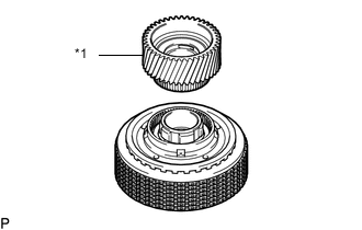
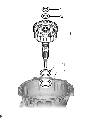
REMOVE C-3 CLUTCH ASSEMBLY
-
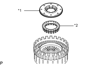
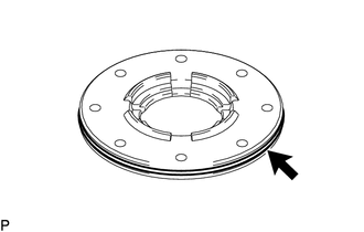
*1 Thrust Needle Roller Bearing *2 C-3 Clutch Assembly Remove the C-3 clutch assembly and thrust needle roller bearing.
-
-
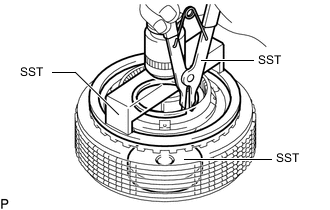
REMOVE NO. 3 CLUTCH DISC
-
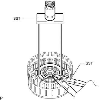
Set SST on the C-3 clutch balancer and compress the direct clutch return spring sub-assembly (C-3 clutch) using a press.
- SST
- 09320-89010
-
Using SST, remove the snap ring from the C-3 drum sub-assembly.
- SST
- 09350-30020 ( 09350-07070 )
-
*1 C-3 Clutch Balancer *2 Direct Clutch Return Spring Sub-assembly (C-3 Clutch) Remove the C-3 clutch balancer and direct clutch return spring sub-assembly (C-3 clutch) from the C-3 drum sub-assembly.
-
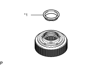
Remove the O-ring from the C-3 clutch balancer.
-
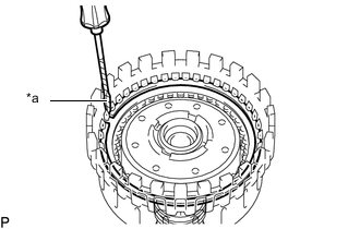
*a Protective Tape Using a screwdriver, remove the snap ring from the C-3 drum sub-assembly.
Note
Be careful not to damage the C-3 drum sub-assembly.
Tech Tips
Tape the screwdriver tip before use.
-
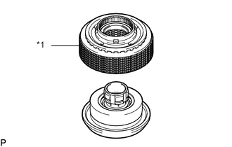
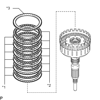
*1 No. 3 Clutch Plate *2 No. 3 Clutch Disc *3 Clutch Flange Remove the 5 No. 3 clutch plates, 5 No. 3 clutch discs and clutch flange from the C-3 drum sub-assembly.
-
-
INSPECT NO. 3 CLUTCH DISC
-
INSPECT DIRECT CLUTCH RETURN SPRING SUB-ASSEMBLY (C-3 CLUTCH)
-
REMOVE C-3 CLUTCH PISTON
-
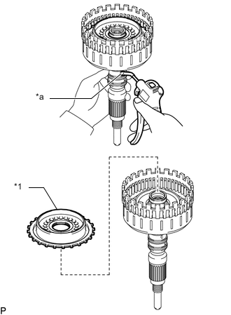
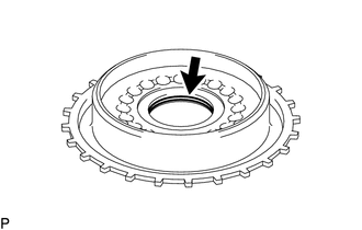
*1 C-3 Clutch Piston *a Oil Hole While holding the C-3 drum sub-assembly, apply compressed air (400 kPa (4.1 kgf/cm2, 58 psi)) to the oil hole to remove the C-3 clutch piston from the C-3 drum sub-assembly.
-
*1 O-ring *2 Oil Seal Ring Remove the 2 O-rings and 2 oil seal rings from the C-3 drum sub-assembly.
-
-
REMOVE NO. 2 BRAKE PISTON
-
Set SST on the 2nd brake piston return spring sub-assembly, automatic transmission case and tighten SST to compress the 2nd brake piston return spring sub-assembly.
- SST
- 09308-14010
- 09380-60012 ( 09381-06010, 09381-06020, 09381-06040, 09381-06050, 09381-06090, 09381-06120, 09381-06150 )
-
Using snap ring expander, remove the hole snap ring from the center support sub-assembly.
-
*1 2nd Brake Piston Return Spring Sub-assembly Remove the 2nd brake piston return spring sub-assembly from the No. 2 brake piston.
-
While holding the automatic transmission case, apply compressed air (400 kPa (4.1 kgf/cm2, 58 psi)) to the oil hole to the No. 2 brake piston to lift it from the center support sub-assembly.
Tech Tips
While evenly and lightly pressing on the No. 2 brake piston using your hand, blow in air a little at a time to remove the No. 2 brake piston smoothly.
-
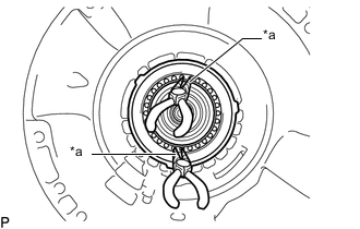
*a Protective Tape Using 2 needle-nose pliers, remove the No. 2 brake piston from the center support sub-assembly.
Note
Be careful not to damage the No. 2 brake piston.
Tech Tips
Tape the tip of needle-nose pliers before use.
-
Remove the O-ring from the No. 2 brake piston.
-
-
INSPECT 2ND BRAKE PISTON RETURN SPRING SUB-ASSEMBLY
-
REMOVE CENTER SUPPORT SUB-ASSEMBLY WITH 1ST AND REVERSE BRAKE PISTON
-
Remove the 2 bolts from the center support sub-assembly with 1st and reverse brake piston.
-
*1 Center Support Sub-assembly with 1st and Reverse Brake Piston Remove the center support sub-assembly with 1st and reverse brake piston from the automatic transmission case.
Tech Tips
If the center support sub-assembly with 1st and reverse brake piston cannot be lifted up and removed by hand:Lightly tap the output shaft using a plastic-faced hammer and remove the center support sub-assembly with 1st and reverse brake piston.
-
-
REMOVE 1ST AND REVERSE BRAKE PISTON
-
*1 1st and Reverse Brake Piston *a Oil Hole While holding the center support sub-assembly, apply compressed air (400 kPa (4.1 kgf/cm2, 58 psi) to the oil hole to remove the 1st and reverse brake piston from the center support sub-assembly.
Tech Tips
While evenly and lightly pressing on the 1st and reverse brake piston using your hand, blow in air a little at a time to remove the 1st and reverse brake piston.
-
Remove the 2 O-rings from the 1st and reverse brake piston.
-
Remove the O-ring from the center support sub-assembly.
-
-
INSPECT CENTER SUPPORT SUB-ASSEMBLY
-
REMOVE CENTER PLANETARY RING GEAR WITH CENTER PLANETARY RING GEAR FLANGE
-
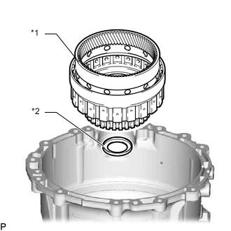
*1 Center Planetary Ring Gear with Center Planetary Ring Gear Flange Remove the center planetary ring gear with center planetary ring gear flange from the rear planetary gear assembly with planetary sun gear sub-assembly and center planetary gear assembly.
-
-
REMOVE CENTER PLANETARY RING GEAR FLANGE
-
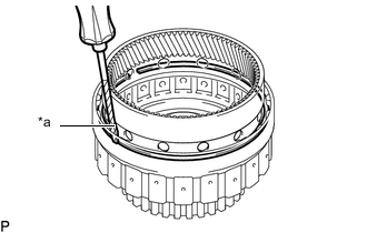
*a Protective Tape Using a screwdriver, remove the snap ring from the center planetary ring gear.
Note
Be careful not to damage the center planetary ring gear.
Tech Tips
Tape the screwdriver tip before use.
-
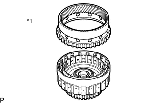
*1 Center Planetary Ring Gear Flange Remove the center planetary ring gear flange from the center planetary ring gear.
-
-
REMOVE REAR PLANETARY GEAR ASSEMBLY WITH PLANETARY SUN GEAR SUB-ASSEMBLY AND CENTER PLANETARY GEAR ASSEMBLY
-
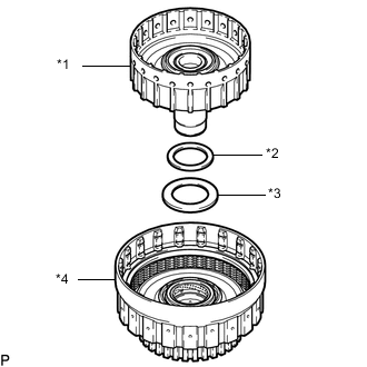
*1 Thrust Needle Roller Bearing *2 Thrust Bearing Race *3 Rear Planetary Gear Assembly with Planetary Sun Gear Sub-assembly and Center Planetary Gear Assembly Remove the rear planetary gear assembly with planetary sun gear sub-assembly and center planetary gear assembly, thrust needle roller bearing and thrust bearing race.
-
-
REMOVE CENTER PLANETARY GEAR ASSEMBLY
-
*1 Center Planetary Gear Assembly Remove the center planetary gear assembly from the rear planetary gear assembly.
-
-
INSPECT CENTER PLANETARY GEAR ASSEMBLY
-
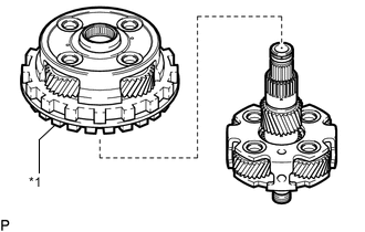
REMOVE PLANETARY SUN GEAR SUB-ASSEMBLY
-
*1 Planetary Sun Gear Sub-assembly Remove the planetary sun gear sub-assembly from the rear planetary gear assembly.
-
Remove the oil seal ring from the rear planetary gear assembly.
-
-
INSPECT PLANETARY SUN GEAR SUB-ASSEMBLY
-
INSPECT REAR PLANETARY GEAR ASSEMBLY
-
REMOVE REAR PLANETARY RING GEAR WITH REAR PLANETARY RING GEAR FLANGE SUB-ASSEMBLY
-
*1 Thrust Needle Roller Bearing *2 Thrust Bearing Race *3 Rear Planetary Ring Gear with Rear Planetary Ring Gear Flange Sub-assembly Remove the rear planetary ring gear with rear planetary ring gear flange sub-assembly, thrust needle roller bearing and thrust bearing race.
-
-
REMOVE REAR PLANETARY RING GEAR FLANGE SUB-ASSEMBLY
-
*a Protective Tape Using a screwdriver, remove the snap ring from the rear planetary ring gear.
Note
Be careful not to damage the rear planetary ring gear.
Tech Tips
Tape the screwdriver tip before use.
-
*1 Rear Planetary Ring Gear Flange Sub-assembly Remove the rear planetary ring gear flange sub-assembly from the rear planetary ring gear.
-
-
INSPECT REAR PLANETARY RING GEAR FLANGE SUB-ASSEMBLY
-
REMOVE OUTPUT SHAFT ASSEMBLY WITH C-4 CLUTCH
-
*1 Thrust Needle Roller Bearing *2 Thrust Bearing Race *3 Output Shaft Assembly with C-4 Clutch Remove the output shaft assembly with C-4 clutch, 2 thrust needle roller bearings and 2 thrust bearing races.
-
-
REMOVE NO. 4 CLUTCH DISC
-
*a Protective Tape Using a screwdriver, remove the snap ring from the output shaft assembly.
Note
Be careful not to damage the output shaft assembly.
Tech Tips
Tape the screwdriver tip before use.
-
*1 No. 4 Clutch Plate *2 No. 4 Clutch Disc *3 Clutch Flange Remove the 6 No. 4 clutch plates, 6 No. 4 clutch discs and clutch flange from the output shaft assembly.
-
-
INSPECT NO. 4 CLUTCH DISC
-
REMOVE C-4 CLUTCH PISTON
-
Set SST on the C-4 clutch balancer and compress the direct clutch return spring sub-assembly (C-4 clutch) using a press.
- SST
- 09387-00020
-
Using SST, remove the snap ring from the output shaft assembly.
- SST
- 09350-30020 ( 09350-07070 )
-
*1 C-4 Clutch Balancer *2 Direct Clutch Return Spring Sub-assembly (C-4 clutch) Remove the C-4 clutch balancer and direct clutch return spring sub-assembly (C-4 clutch) from the output shaft assembly.
-
Remove the O-ring from the C-4 clutch balancer.
-
*1 C-4 Clutch Piston *a Oil Hole While holding the output shaft assembly, apply compressed air (400 kPa (4.1 kgf/cm2, 58 psi)) to the oil hole to remove the C-4 clutch piston from the output shaft assembly.
-
Remove the O-ring from the C-4 clutch piston.
-
Remove the O-ring from the output shaft assembly.
-
Remove the 3 clutch drum oil seal rings from the output shaft assembly.
-
-
INSPECT DIRECT CLUTCH RETURN SPRING SUB-ASSEMBLY (C-4 CLUTCH)
-
REMOVE BRAKE PLATE STOPPER SPRING
-
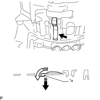
*a End of brake plate stopper spring Pull lightly on the end Remove in the direction of the arrow Remove the brake plate stopper spring.
-
Pull lightly on the end of the brake plate stopper spring.
-
Remove the brake plate stopper spring from the automatic transmission case in the direction indicated by the arrow.
-
-
-
REMOVE FLANGE YOKE TYPE T OIL SEAL
-
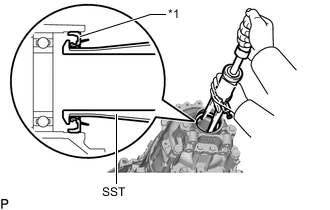
*1 Flange Yoke Type T Oil Seal Using SST, remove the flange yoke type T oil seal from the automatic transmission case.
- SST
- 09308-36010
Note
When removing the flange yoke type T oil seal, make sure not to damage the output shaft or automatic transmission case.
-
-
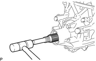
REMOVE OUTPUT SHAFT REAR RADIAL BALL BEARING
-
*a Hold Turn Using SST, remove the output shaft rear radial ball bearing from the automatic transmission case.
- SST
- 09612-65014 ( 09612-01060 )
-
-
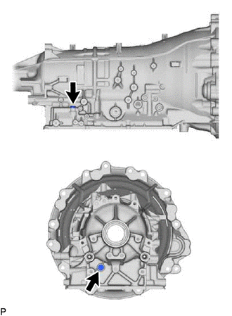
REMOVE AUTOMATIC TRANSMISSION CASE PLUG
Tech Tips
If automatic transmission fluid leaks from a automatic transmission case plug or the plug is corroded, replace it.
-
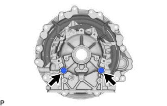
for T55 "TORX":
-
Using a T55 "TORX" socket wrench, remove the 2 automatic transmission case plugs and 2 O-rings from the automatic transmission case.
-
-
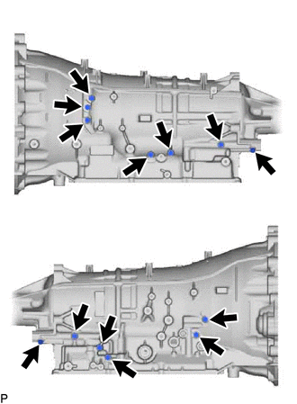
for 12 mm head:
-
Remove the 13 automatic transmission case plugs and 13 O-rings from the automatic transmission case.
-
-
for 24 mm head:
-
Remove the 2 automatic transmission case plugs and 2 O-rings from the automatic transmission case.
-
-
-
INSPECT AUTOMATIC TRANSMISSION CASE