ТОПЛИВНАЯ СИСТЕМА
-
CONSTRUCTION
-
Each injector assembly consists of a nozzle needle, a control plate and a solenoid valve.
-
An injector compensation value and a Quick Response (QR) code containing encoded characteristics of the injector are printed on each injector.
-
The injector compensation value and QR code contain various pieces of information regarding the injector, such as model code and injection volume correction.
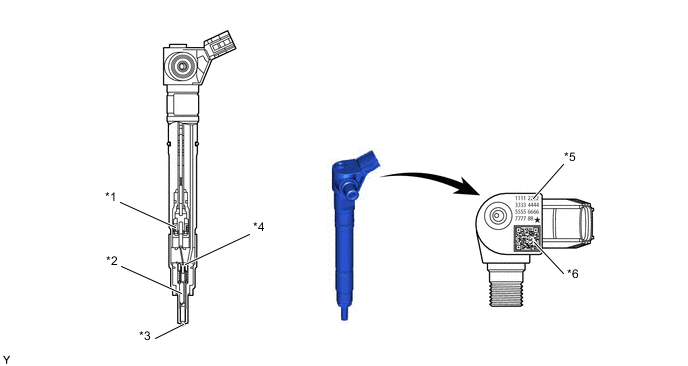
*1 Solenoid *2 Nozzle Needle *3 Low Suck Volume Nozzle *4 Control Plate *5 Injector Compensation Value *6 QR Code
-
-
OPERATION
-
When electrical current is applied to the solenoid coil, it pulls the solenoid valve up.
-
The out-orifice of the control chamber opens, allowing the fuel to flow out.
-
The fuel pressure in the control chamber drops.
-
Simultaneously, nozzle needle lifts and fuel is injected.
-
As the control valve closes, the pressure of the control camber and intermediate chamber are equalized.
-
The control plate is pushed down by in-orifice pressure, allowing fuel to flow to the control chamber.
-
As control chamber pressure increases, the nozzle needle closes with the force of the spring and fuel injection is stopped.
-
When the control chamber and in-orifice pressure equalize, the control plate rises due to the force of the spring.
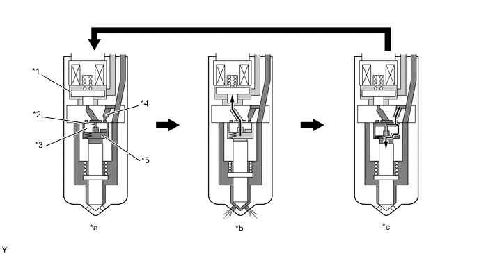
*1 Control Valve *2 Out-orifice *3 Control Plate *4 In-orifice *5 Control Chamber - - *a Before fuel injection *b Fuel injection *c After fuel injection - - 
High Fuel Pressure 
Low Fuel Pressure
-