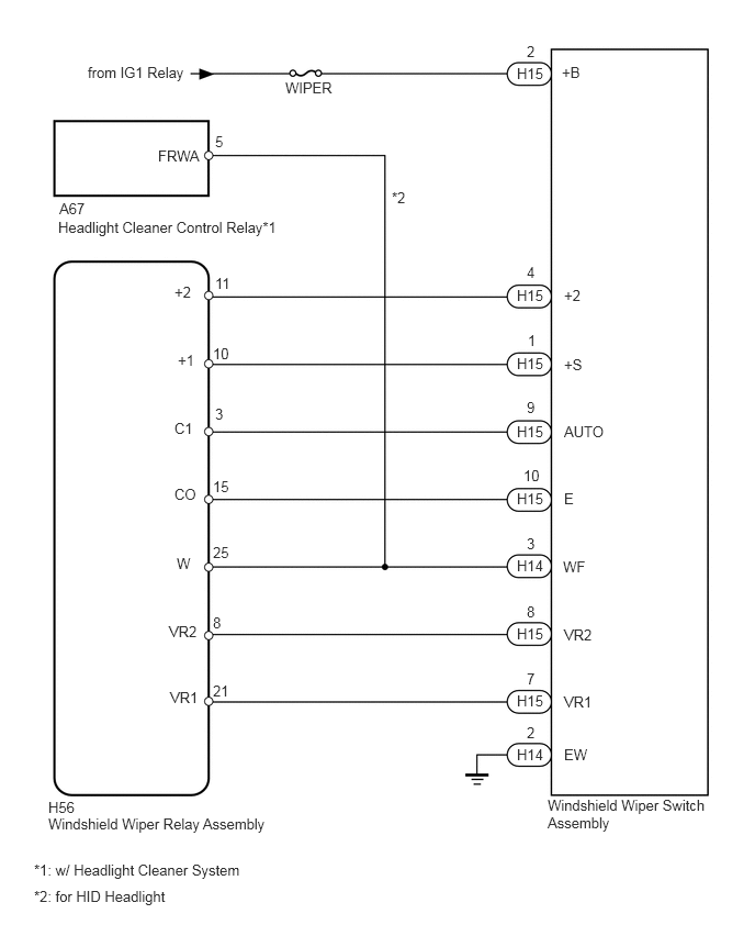
WIPER AND WASHER SYSTEM(w/ Rain Sensor) Wiper and Washer Switch Circuit
| DTC Code | DTC Name |
|---|---|
| Wiper and Washer Switch Circuit |
DESCRIPTION
This circuit provides power to operate the windshield wiper switch assembly. The manual operation signals are sent to the windshield wiper relay assembly.
WIRING DIAGRAM
CAUTION / NOTICE / HINT
Inspect the fuses for circuits related to this system before performing the following inspection procedure.
PROCEDURE
CHECK HARNESS AND CONNECTOR (WINDSHIELD WIPER SWITCH - BATTERY)
-
Disconnect the H15 switch connector.
Measure the voltage according to the value(s) in the table below.
Standard Voltage
Tester Connection
Switch Condition
Specified Condition
H15-2 (+B) - Body ground
Ignition switch ON
11 to 14 V
H15-2 (+B) - Body ground
Ignition switch off
Below 1 V
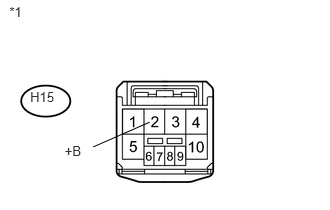
Table 1. Text in Illustration *1
Front view of wire harness connector
(to Windshield Wiper Switch Assembly)
REPAIR OR REPLACE HARNESS OR CONNECTOR
-
INSPECT WINDSHIELD WIPER SWITCH ASSEMBLY
-
Remove the windshield wiper switch assembly (Click here).
Measure the resistance according to the value(s) in the table below.
Standard Resistance
Tester Connection
Switch Condition
Specified Condition
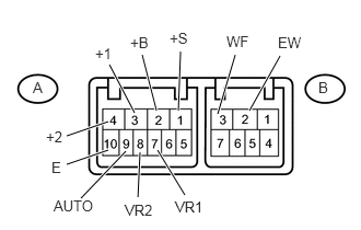
A-3 (+1) - A-1 (+S)
Front wiper switch off
Below 1 Ω
A-3 (+1) - A-2 (+B)
Front wiper switch MIST
Front wiper switch LO
A-2 (+B) - A-4 (+2)
Front wiper switch HI
A-9 (AUTO) - A-10 (E)
Front wiper switch AUTO
A-8 (VR2) - A-7 (VR1)
Adjusting ring* changed from (+) side to (-) side
Below 10 to 2700 Ω
B-2 (EW) - B-3 (WF)
Front washer switch on
Below 1 Ω
Front washer switch off
10 kΩ or higher
Tip:*: The rain sensor sensitivity can be adjusted by the windshield wiper switch assembly adjusting ring.
-
CHECK HARNESS AND CONNECTOR (WIPER SWITCH - WIPER RELAY, HEADLIGHT CLEANER CONTROL RELAY AND BODY GROUND)
*1: w/ Headlight Cleaner System
Disconnect the H14 and H15 switch connectors.
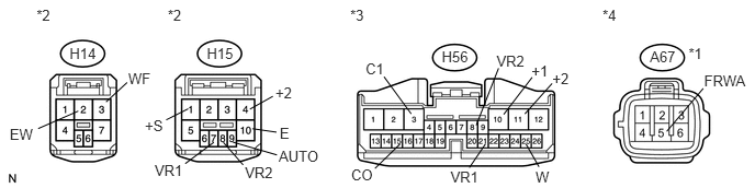
Disconnect the H56 relay connector.
Disconnect the A67*1 control relay connector.
Measure the resistance according to the value(s) in the table below.
Standard Resistance
w/ Headlight Cleaner System
Tester Connection
Condition
Specified Condition
H15-4 (+2) - H56-11 (+2)
Always
Below 1 Ω
H15-4 (+2) - Body ground
Always
10 kΩ or higher
H15-1 (+S) - H56-10 (+1)
Always
Below 1 Ω
H15-1 (+S) - Body ground
Always
10 kΩ or higher
H15-9 (AUTO) - H56-3 (C1)
Always
Below 1 Ω
H15-9 (AUTO) - Body ground
Always
10 kΩ or higher
H15-10 (E) - H56-15 (CO)
Always
Below 1 Ω
H15-10 (E) - Body ground
Always
10 kΩ or higher
H14-3 (WF) - H56-25 (W)
Always
Below 1 Ω
H14-3 (WF) - Body ground
Always
10 kΩ or higher
H15-8 (VR2) - H56-8 (VR2)
Always
Below 1 Ω
H15-8 (VR2) - Body ground
Always
10 kΩ or higher
H15-7 (VR1) - H56-21 (VR1)
Always
Below 1 Ω
H15-7 (VR1) - Body ground
Always
10 kΩ or higher
H14-2 (EW) - Body ground
Always
Below 1 Ω
A67-5 (FRWA) - H14-3 (WF)
Always
Below 1 Ω
A67-5 (FRWA) - H56-25 (W)
Always
Below 1 Ω
A67-5 (FRWA) - Body ground
Always
10 kΩ or higher
Standard Resistance
w/o Headlight Cleaner System
Tester Connection
Condition
Specified Condition
H15-4 (+2) - H56-11 (+2)
Always
Below 1 Ω
H15-4 (+2) - Body ground
Always
10 kΩ or higher
H15-1 (+S) - H56-10 (+1)
Always
Below 1 Ω
H15-1 (+S) - Body ground
Always
10 kΩ or higher
H15-9 (AUTO) - H56-3 (C1)
Always
Below 1 Ω
H15-9 (AUTO) - Body ground
Always
10 kΩ or higher
H15-10 (E) - H56-15 (CO)
Always
Below 1 Ω
H15-10 (E) - Body ground
Always
10 kΩ or higher
H14-3 (WF) - H56-25 (W)
Always
Below 1 Ω
H14-3 (WF) - Body ground
Always
10 kΩ or higher
H15-8 (VR2) - H56-8 (VR2)
Always
Below 1 Ω
H15-8 (VR2) - Body ground
Always
10 kΩ or higher
H15-7 (VR1) - H56-21 (VR1)
Always
Below 1 Ω
H15-7 (VR1) - Body ground
Always
10 kΩ or higher
H14-2 (EW) - Body ground
Always
Below 1 Ω
Table 2. Text in Illustration *1
w/ Headlight Cleaner System
*2
Front view of wire harness connector
(to Windshield Wiper Switch Assembly)
*3
Front view of wire harness connector
(to Windshield Wiper Relay Assembly)
*4
Front view of wire harness connector
(to Headlight Cleaner Control Relay)
REPAIR OR REPLACE HARNESS OR CONNECTOR