ION GENERATOR INSTALLATION
CAUTION / NOTICE / HINT
Tech Tips
-
Use the same procedure for RHD and LHD vehicles.
-
The procedure listed below is for LHD vehicles.
PROCEDURE
-
INSTALL ION GENERATOR SUB-ASSEMBLY
-
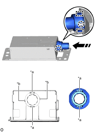
*a Guide *b Claw 
Align with the guide position and insert in a straight line Align the guide, attach the claw and install the air duct sub-assembly to the ion generator sub-assembly as shown in the illustration.
-

Screw 
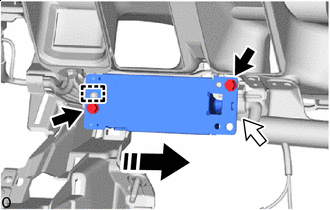
Air duct Insert in this Direction for LHD:
-
Insert the ion generator sub-assembly with air duct sub-assembly in the direction of the arrow shown in the illustration, and then insert the air duct sub-assembly into the No. 3 heater to register duct sub-assembly as shown in the illustration.
-
Set the guide into place and install the ion generator sub-assembly with air duct sub-assembly with the 2 screws.
-
-
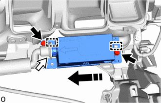
Screw Air duct Insert in this Direction for RHD:
-
Insert the ion generator sub-assembly with air duct sub-assembly in the direction of the arrow shown in the illustration, and then insert the air duct sub-assembly into the No. 3 heater to register duct sub-assembly as shown in the illustration.
-
Set the guide into place and install the ion generator sub-assembly with air duct sub-assembly with the 2 screws.
-
-
-
INSTALL INSTRUMENT PANEL SAFETY PAD SUB-ASSEMBLY
-
CONNECT CABLE TO NEGATIVE BATTERY TERMINAL
-
for 8GR-FKS:
-
for V35A-FTS:
Note
When disconnecting the cable, some systems need to be initialized after the cable is reconnected.
-
-
INSTALL LUGGAGE COMPARTMENT MAT SUB-ASSEMBLY
-
PERFORM DIAGNOSTIC SYSTEM CHECK
-
INSPECT SRS WARNING LIGHT