Install the front lower coil spring insulator LH to the front shock absorber assembly.
Note:
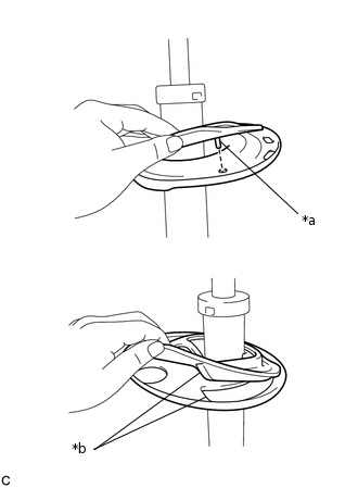
When installing the insulator, fit the insulator into the depression of the spring seat and insert the positioning pin into the hole.
INSTALL FRONT SPRING BUMPER LH
Install the front spring bumper LH to the front shock absorber assembly.
Note:
Position the end of the front spring bumper with the smaller diameter downward.
INSTALL FRONT COIL SPRING LH
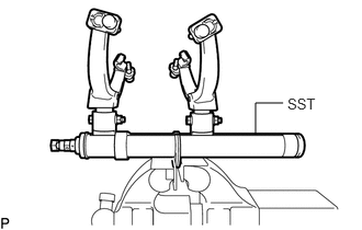
For SST with stopper pins:
Secure SST in a vise.
09727-30022
09727-00010
09727-00022
09727-00031
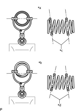
*a
Correct
*b
Incorrect
*c
Parallel
*d
Not Parallel
Attach the hooks of each SST arm across the diameter of the coil spring.
CAUTION:
Make sure that the hooks of the upper and lower arms are attached to the coil spring so that the distance between the hooks is as large as possible.
Make sure that the arms of SST are parallel and attached to the coil spring, and the number of coil springs between the hooks on each side is the same.
Check that the claws of the hooks are securely attached to the coil spring.
*a
Correct
*b
Incorrect
*c
Stopper Pin
Install the stopper pins to the hooks of SST.
CAUTION:
Make sure that the stopper pins are installed securely.
Using SST, compress the coil spring.
CAUTION:
If the coil spring bends while using SST, stop immediately and reattach SST correctly.
Do not compress the coil spring to the point where the coils touch each other.
Do not use an impact wrench.
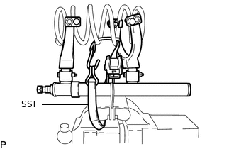
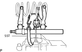
If a stopper pin touches the coil spring while using SST, remove the stopper pin and continue with the procedure. In this case, installing the coil spring stopper belt as shown in the illustration is recommended.
09727-00110
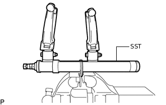
For SST without stopper pins:
Secure SST in a vise.
09727-30021
09727-00010
09727-00021
09727-00031
*a
Correct
*b
Incorrect
*c
Parallel
*d
Not Parallel
Attach the hooks of each SST arm across the diameter of the coil spring.
CAUTION:
Make sure that the hooks of the upper and lower arms are attached to the coil spring so that the distance between the hooks is as large as possible.
Make sure that the arms of SST are parallel and attached to the coil spring, and the number of coil springs between the hooks on each side is the same.
Check that the claws of the hooks are securely attached to the coil spring.
Using SST, compress the coil spring.
CAUTION:
If the coil spring bends while using SST, stop immediately and reattach SST correctly.
Do not compress the coil spring to the point where the coils touch each other.
Do not use an impact wrench.
Tip:
Installing SST as shown in the illustration is recommended.
09727-00110
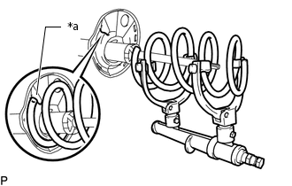
*a
Depression
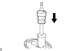
Install the front coil spring to the front shock absorber assembly.
Note:
Make sure to fit the end of the front coil spring that has the larger diameter into the depression of the front lower coil spring insulator LH.
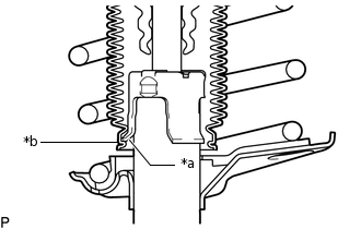
INSTALL FRONT SPRING SEAT SUB-ASSEMBLY LH WITH INSULATOR
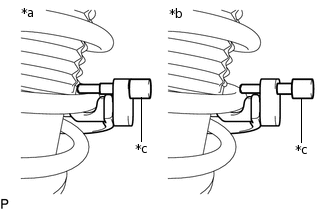
*a
Claws of the Front Shock Absorber Assembly LH
*b
End of the Insulator of the Front Spring Seat Sub-assembly LH with Insulator
Connect the end of the insulator of the front spring seat sub-assembly LH with insulator with the claws of the front shock absorber assembly LH.
Note:
Make sure that the end of the insulator is securely attached to the claws of the front shock absorber assembly LH.
Make sure there is no excessive damage to the bellows of the insulator.
Do not allow oil, grease, etc., to contact the insulator.
If oil or grease has adhered, wipe clean with a cloth. Do not use an alcoholic cleaner.
INSTALL STRUT MOUNTING BEARING LH
INSTALL FRONT SUSPENSION SUPPORT SUB-ASSEMBLY LH
Install the front suspension support sub-assembly LH to the front shock absorber assembly LH.
INSTALL COLLAR
Install the collar to the front shock absorber assembly LH.
TEMPORARILY INSTALL FRONT SUPPORT TO FRONT SHOCK ABSORBER NUT
Temporarily install a new front support to front shock absorber nut.
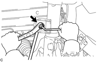
Remove SST from the front coil spring.
Note:
Do not use an impact wrench. It will damage SST.
INSTALL FRONT SUSPENSION SUPPORT PLATE LH
Install the front suspension support plate to the front shock absorber with coil spring.
INSTALL FRONT SHOCK ABSORBER WITH COIL SPRING
Install the front shock absorber with coil spring (upper side) and cowl body mounting reinforcement LH with the 3 nuts.
50 N*m
510 kgf*cm
37 ft.*lbf
Connect the front shock absorber with coil spring (lower side) to the steering knuckle with the 2 bolts and 2 nuts.
240 N*m
2447 kgf*cm
177 ft.*lbf
Tip:
The bolts can be installed in either direction, however, make sure that they are both installed in the same direction.
Tighten the front support to front shock absorber nut.