POWER DOOR LOCK CONTROL SYSTEM All Doors cannot be Locked / Unlocked Simultaneously
DESCRIPTION
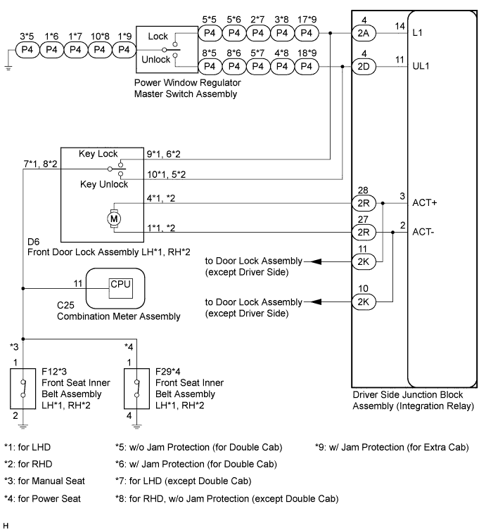
The driver side junction block assembly drives the door lock motors according to switch signals from the door control switch of the power window regulator master switch assembly and the driver side door key cylinder.
However, the driver side door key-linked lock/unlock function will not operate when the driver side seat belt is fastened.
WIRING DIAGRAM
INSPECTION PROCEDURE
PROCEDURE
-
CHECK POWER DOOR LOCK OPERATION
-
Check the power door lock operation.
Result Result Proceed to No doors can be locked using power window regulator master switch assembly (door control switch) A No doors can be locked using key-linked switch B
B 
INSPECT FRONT DOOR LOCK ASSEMBLY (DRIVER SIDE) Click here
A 
-
-
INSPECT POWER WINDOW REGULATOR MASTER SWITCH ASSEMBLY (DOOR CONTROL SWITCH)
-
Remove the power window regulator master switch assembly.
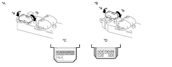
Text in Illustration *A for LHD *B for RHD *C for Double Cab, except Double Cab (w/ Jam Protection Function) *D for Single Cab, except Double Cab (w/o Jam Protection Function) *a Lock *b Unlock -
Measure the resistance according to the value(s) in the table below.
Standard Resistance w/ Jam Protection (for Double Cab) Tester Connection Switch Condition Specified Condition 3 - 5 Lock Below 1 Ω 3 - 5, 3 - 8 OFF 10 kΩ or higher 3 - 8 Unlock Below 1 Ω w/o Jam Protection (for Double Cab) Tester Connection Switch Condition Specified Condition 1 - 5 Lock Below 1 Ω 1 - 5, 1 - 8 OFF 10 kΩ or higher 1 - 8 Unlock Below 1 Ω for LHD (except Double Cab) Tester Connection Switch Condition Specified Condition 1 - 2 Lock Below 1 Ω 1 - 2, 1 - 5 OFF 10 kΩ or higher 1 - 5 Unlock Below 1 Ω for RHD, w/o Jam Protection (except Double Cab) Tester Connection Switch Condition Specified Condition 3 - 10 Lock Below 1 Ω 3 - 10, 4 - 10 OFF 10 kΩ or higher 4 - 10 Unlock Below 1 Ω w/ Jam Protection (for Extra Cab) Tester Connection Switch Condition Specified Condition 1 - 17 Lock Below 1 Ω 1 - 17, 1 - 18 OFF 10 kΩ or higher 1 - 18 Unlock Below 1 Ω
NG 
REPLACE POWER WINDOW REGULATOR MASTER SWITCH ASSEMBLY
OK
-
-
CHECK HARNESS AND CONNECTOR (POWER WINDOW REGULATOR MASTER SWITCH - DRIVER SIDE JUNCTION BLOCK AND BODY GROUND)
-
Disconnect the P4 power window regulator master switch assembly connector.
-
Disconnect the 2A and 2D driver side junction block assembly connectors.
-
Measure the resistance according to the value(s) in the table below.
Standard Resistance w/ Jam Protection (for Double Cab) Tester Connection Condition Specified Condition P4-5 - 2A-4 (L1) Always Below 1 Ω P4-8 - 2D-4 (UL1) Always Below 1 Ω P4-3 - Body ground Always Below 1 Ω P4-5 or 2A-4 (L1) - Body ground Always 10 kΩ or higher P4-8 or 2D-4 (UL1) - Body ground Always 10 kΩ or higher w/o Jam Protection (for Double Cab) Tester Connection Condition Specified Condition P4-5 - 2A-4 (L1) Always Below 1 Ω P4-8 - 2D-4 (UL1) Always Below 1 Ω P4-1 - Body ground Always Below 1 Ω P4-5 or 2A-4 (L1) - Body ground Always 10 kΩ or higher P4-8 or 2D-4 (UL1) - Body ground Always 10 kΩ or higher for LHD (except Double Cab) Tester Connection Condition Specified Condition P4-2 - 2A-4 (L1) Always Below 1 Ω P4-5 - 2D-4 (UL1) Always Below 1 Ω P4-1 - Body ground Always Below 1 Ω P4-2 or 2A-4 (L1) - Body ground Always 10 kΩ or higher P4-5 or 2D-4 (UL1) - Body ground Always 10 kΩ or higher for RHD, w/o Jam Protection (except Double Cab) Tester Connection Condition Specified Condition P4-3 - 2A-4 (L1) Always Below 1 Ω P4-4 - 2D-4 (UL1) Always Below 1 Ω P4-10 - Body ground Always Below 1 Ω P4-3 or 2A-4 (L1) - Body ground Always 10 kΩ or higher P4-4 or 2D-4 (UL1) - Body ground Always 10 kΩ or higher w/ Jam Protection (for Extra Cab) Tester Connection Condition Specified Condition P4-17 - 2A-4 (L1) Always Below 1 Ω P4-18 - 2D-4 (UL1) Always Below 1 Ω P4-1 - Body ground Always Below 1 Ω P4-17 or 2A-4 (L1) - Body ground Always 10 kΩ or higher P4-18 or 2D-4 (UL1) - Body ground Always 10 kΩ or higher
NG
REPAIR OR REPLACE HARNESS OR CONNECTOR
OK 
REPLACE DRIVER SIDE JUNCTION BLOCK ASSEMBLY
-
-
INSPECT FRONT DOOR LOCK ASSEMBLY (DRIVER SIDE)
-
Remove the front door lock assembly LH*1 or RH*2.
-
*1: for LHD
-
*2: for RHD
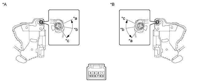
Text in Illustration *A for LHD *B for RHD *a Lock *b Off *c Unlock - - -
-
Measure the resistance according to the value(s) in the table below.
Standard Resistance for LHD Tester Connection Switch Condition Specified Condition 7 - 9 Lock Below 1 Ω 7 - 9, 7 - 10 Off 10 kΩ or higher 7 - 10 Unlock Below 1 Ω for RHD Tester Connection Switch Condition Specified Condition 6 - 8 Lock Below 1 Ω 5 - 8, 6 - 8 Off 10 kΩ or higher 5 - 8 Unlock Below 1 Ω
NG
REPLACE FRONT DOOR LOCK ASSEMBLY (DRIVER SIDE)
OK
-
-
CHECK SEAT BELT WARNING SYSTEM
-
Turn the ignition switch to ON.
-
When the driver side seat belt is not fastened, check that the driver side seat belt warning light in the combination meter assembly blinks.
-
When the driver side seat belt is fastened, check that the driver side seat belt warning light in the combination meter assembly turns off.
OK Driver side seat belt warning light blinks and turns off according to above operation.
NG
Go to SEAT BELT WARNING SYSTEM Click here
OK
-
-
CHECK HARNESS AND CONNECTOR (FRONT SEAT INNER BELT - FRONT DOOR LOCK)
-
*1: for LHD
-
*2: for RHD
-
for Manual Seat:
-
Disconnect F12 front seat inner belt assembly LH*1 or RH*2 connector.
-
Disconnect the D6 front door lock assembly LH*1 or RH*2 connector.
-
Measure the resistance according to the value(s) in the table below.
Standard Resistance for LHD Tester Connection Condition Specified Condition F12-1 - D6-7 Always Below 1 Ω F12-1 or D6-7 - Body ground Always 10 kΩ or higher for RHD Tester Connection Condition Specified Condition F12-1 - D6-8 Always Below 1 Ω F12-1 or D6-8 - Body ground Always 10 kΩ or higher
-
-
for Power Seat:
-
Disconnect F29 front seat inner belt assembly LH*1 or RH*2 connector.
-
Disconnect the D6 front door lock assembly LH*1 or RH*2 connector.
-
Measure the resistance according to the value(s) in the table below.
Standard Resistance for LHD Tester Connection Condition Specified Condition F29-1 - D6-7 Always Below 1 Ω F29-1 or D6-7 - Body ground Always 10 kΩ or higher for RHD Tester Connection Condition Specified Condition F29-1 - D6-8 Always Below 1 Ω F29-1 or D6-8 - Body ground Always 10 kΩ or higher
-
NG
REPAIR OR REPLACE HARNESS OR CONNECTOR
OK
-
-
CHECK HARNESS AND CONNECTOR (FRONT DOOR LOCK - DRIVER SIDE JUNCTION BLOCK AND BODY GROUND)
-
Disconnect the D6 front door lock assembly connector.
-
Disconnect the 2A and 2D driver side junction block assembly (integration relay) connectors.
-
Measure the resistance according to the value(s) in the table below.
Standard Resistance for LHD Tester Connection Condition Specified Condition D6-10 - 2D-4 (UL1) Always Below 1 Ω D6-9 - 2A-4 (L1) Always Below 1 Ω D6-7 - Body ground Driver seat belt is not fastened Below 1 Ω D6-10 or 2D-4 (UL1) - Body ground Always 10 kΩ or higher D6-9 or 2A-4 (L1) - Body ground Always 10 kΩ or higher for RHD Tester Connection Condition Specified Condition D6-5 - 2D-4 (UL1) Always Below 1 Ω D6-6 - 2A-4 (L1) Always Below 1 Ω D6-8 - Body ground Driver seat belt is not fastened Below 1 Ω D6-5 or 2D-4 (UL1) - Body ground Always 10 kΩ or higher D6-6 or 2A-4 (L1) - Body ground Always 10 kΩ or higher
NG
REPAIR OR REPLACE HARNESS OR CONNECTOR
OK
REPLACE DRIVER SIDE JUNCTION BLOCK ASSEMBLY
-