STOP AND START SYSTEM CANCEL SWITCH ASSEMBLY INSPECTION
PROCEDURE
INSPECT STOP AND START SYSTEM CANCEL SWITCH (for 2WW)
-
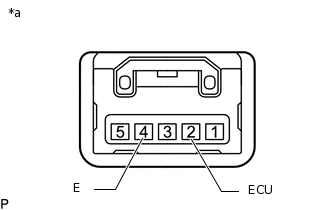
*a
Component without harness connected
(Stop and Start System Cancel Switch)
Measure the resistance according to the value(s) in the table below.
Standard Resistance
Tester Connection
Switch Condition
Specified Condition
2 (ECU) - 4 (E)
Pushed
Below 1 Ω
Not pushed
10 kΩ or higher
If the result is not as specified, replace the stop and start system cancel switch.
-
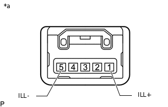
*a
Component without harness connected
(Stop and Start System Cancel Switch)
Apply battery voltage between the terminals of the switch, and check the illumination condition of the stop and start system cancel switch.
OK
Measurement Condition
Specified Condition
Battery positive (+) → 1 (ILL+)
Battery negative (-) → 5 (ILL-)
Illuminates
If the result is not as specified, replace the stop and start system cancel switch.
-
INSPECT STOP AND START SYSTEM CANCEL SWITCH (for 3ZR-FAE)
for Manual Transaxle:
-
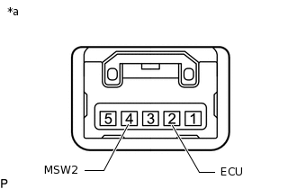
*a
Component without harness connected
(Stop and Start System Cancel Switch)
Measure the resistance according to the value(s) in the table below.
Standard Resistance
Tester Connection
Switch Condition
Specified Condition
2 (ECU) - 4 (MSW2)
Pushed
Below 1 Ω
Not pushed
10 kΩ or higher
If the result is not as specified, replace the stop and start system cancel switch.
-
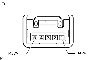
*a
Component without harness connected
(Stop and Start System Cancel Switch)
Apply battery voltage between the terminals of the switch, and check the illumination condition of the stop and start system cancel switch.
OK
Measurement Condition
Specified Condition
Battery positive (+) → 1 (MSW+)
Battery negative (-) → 5 (MSW-)
Illuminates
If the result is not as specified, replace the stop and start system cancel switch.
-
for CVT:
-
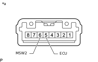
*a
Component without harness connected
(Stop and Start System Cancel Switch)
Measure the resistance according to the value(s) in the table below.
Standard Resistance
Tester Connection
Switch Condition
Specified Condition
5 (ECU) - 6 (MSW2)
Pushed
Below 1 Ω
Not pushed
10 kΩ or higher
If the result is not as specified, replace the stop and start system cancel switch.
-
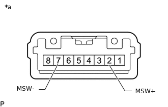
*a
Component without harness connected
(Stop and Start System Cancel Switch)
Apply battery voltage between the terminals of the switch, and check the illumination condition of the stop and start system cancel switch.
OK
Measurement Condition
Specified Condition
Battery positive (+) → 2 (MSW+)
Battery negative (-) → 7 (MSW-)
Illuminates
If the result is not as specified, replace the stop and start system cancel switch.
-