FRONT STABILIZER BAR REMOVAL
CAUTION / NOTICE / HINT
The necessary procedures (adjustment, calibration, initialization, or registration) that must be performed after parts are removed and installed, or replaced during front stabilizer bar removal/installation are shown below.
| Replaced Part or Performed Procedure | Necessary Procedure | Effect/Inoperative Function when Necessary Procedure not Performed | Link |
|---|---|---|---|
| Front wheel alignment adjustment |
|
|
|
| Gas leak from exhaust system is repaired | Inspection After Repair |
|
for 8AR-FTS (for Rear Air Fuel Ratio Sensor): Click here for 8AR-FTS (for Rear Heated Oxygen Sensor): Click here for 2GR-FKS (w/ Canister Pump Module): Click here for 2GR-FKS (w/o Canister Pump Module): Click here |
PROCEDURE
-
ALIGN FRONT WHEELS FACING STRAIGHT AHEAD
-
SECURE STEERING WHEEL
-
REMOVE FRONT WHEELS
-
REMOVE NO. 2 ENGINE UNDER COVER
for 2GR-FKS: Click here
for 8AR-FTS: Click here
-
REMOVE FRONT FLOOR COVER LH (for 2GR-FKS)
-
SEPARATE STEERING INTERMEDIATE SHAFT ASSEMBLY
-
REMOVE FRONT STABILIZER LINK ASSEMBLY LH
-
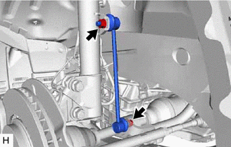
Remove the 2 nuts and front stabilizer link assembly LH from the front shock absorber assembly and front stabilizer bar.
Note
Do not damage the boot of the ball joint.
Tech Tips
If the ball joint turns together with the nut, use a 6 mm hexagon socket wrench to hold the stud bolt.
-
-
REMOVE FRONT STABILIZER LINK ASSEMBLY RH
Tech Tips
Perform the same procedure as for the LH side.
-
SEPARATE TIE ROD ASSEMBLY LH
-
SEPARATE TIE ROD ASSEMBLY RH
Tech Tips
Perform the same procedure as for the LH side.
-
SEPARATE FRONT LOWER NO. 1 SUSPENSION ARM SUB-ASSEMBLY LH
-
REMOVE FRONT NO. 3 EXHAUST PIPE SUB-ASSEMBLY (for 2GR-FKS)
-
DISCONNECT AIR FUEL RATIO SENSOR (for 2GR-FKS)
-

Disconnect the air fuel ratio sensor connector.
-
Disengage the 3 wire harness clamps.
-
-
REMOVE MANIFOLD STAY (for 2GR-FKS)
-
REMOVE EXHAUST MANIFOLD (TWC: Front Catalyst) (for 2GR-FKS)
-
REMOVE EXHAUST MANIFOLD TO HEAD GASKET (for 2GR-FKS)
-
REMOVE FRONT NO. 1 STABILIZER BRACKET LH
-
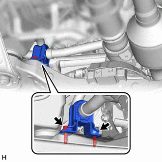
Remove the 2 bolts and front No. 1 stabilizer bracket LH from the front frame assembly.
-
Remove the front No. 2 stabilizer bracket LH from the front frame assembly.
-
-
REMOVE FRONT NO. 1 STABILIZER BRACKET RH
Tech Tips
Perform the same procedure as for the LH side.
-
SEPARATE FRONT STABILIZER BAR
-
REMOVE STEERING LINK ASSEMBLY
-
REMOVE FRONT STABILIZER BAR
-
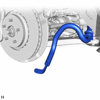
Remove the front stabilizer bar with the 2 front stabilizer bar bushings from the vehicle body.
-
-
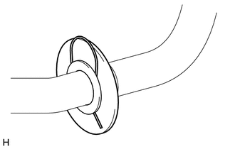
REMOVE FRONT STABILIZER BAR BUSHING LH
-
Remove the front stabilizer bar bushing LH from the front stabilizer bar.
-
-
REMOVE FRONT STABILIZER BAR BUSHING RH
-
Remove the front stabilizer bar bushing RH from the front stabilizer bar.
-
w/ front stabilizer bar protector:
-
Remove the clip.
-
Remove the front stabilizer bar protector from the front stabilizer bar.
-
-