PROPELLER SHAFT ASSEMBLY (for TSAM Made) DISASSEMBLY
-
INSPECT UNIVERSAL JOINT SPIDER ASSEMBLY
-
Check the spider bearings for wear or damage.
-
Check each spider bearing's axial play by turning the yoke while holding the shaft tightly.
Maximum bearing axial play 0 to 0.05 mm (0 to 0.002 in.) If the axial play is greater than the maximum, replace the spider bearing.
-
-
REMOVE REAR SLIDING SHAFT BOOT (for 4WD)
-
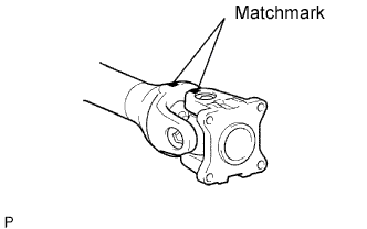
Place matchmarks on the propeller shaft and sleeve yoke.
-
Using a side cutter or pliers, remove the small and large boot clamps.
-
Disconnect the boot from the sleeve yoke.
-
Remove the sleeve yoke, and then remove the boot from the propeller shaft.
-
-
REMOVE UNIVERSAL JOINT SPIDER ASSEMBLY
-
Place matchmarks on the yokes.
-
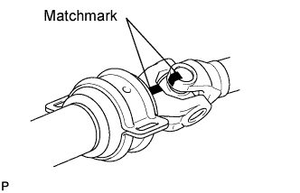
Place matchmarks on the center yoke and the part it is connected to (yoke or shaft).
-
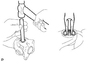
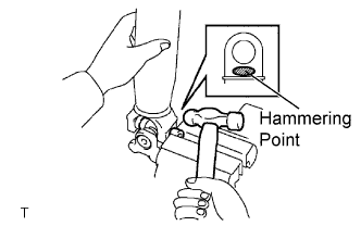
Using a brass bar and hammer, slightly tap in the spider bearing outer races.
-
Using needle nose pliers, remove the 4 snap rings from the grooves.
-
Clamp the propeller shaft in a vise between aluminum plates.
-
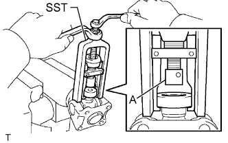
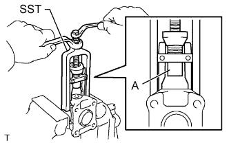
Using SST, push the sleeve yoke side spider bearing until: 1) the spider almost touches the sleeve yoke or propeller shaft, and 2) the spider bearing on the opposite side is partially pushed out.
- SST
- 09332-25010
Tech Tips
Before installing SST, sufficiently raise the part labeled A. If part A is too low, SST may be difficult to install.
-
Clamp the pushed out spider bearing outer race in a vise and tap the propeller shaft to remove the spider bearing.
Note
Do not tap the shaft tube.
Tech Tips
Remove the spider bearing from the opposite side of the spider using the same procedure.
-
Separate the flange yoke and spider from the propeller shaft.
-
Reinstall the 2 removed spider bearings to the spider and clamp the spider bearings in a vise.
-
Using SST, push the flange yoke side spider bearing until: 1) the spider almost touches the flange yoke, and 2) the spider bearing on the opposite side is partially pushed out.
- SST
- 09332-25010
Tech Tips
Before installing SST, sufficiently raise the part labeled A. If part A is too low, SST may be difficult to install.
-
Clamp the pushed out spider bearing outer race in a vise and tap the flange yoke to remove the spider bearing.
Tech Tips
Remove the spider bearing from the opposite side of the spider using the same procedure.
-
Separate the spider from the flange yoke.
Tech Tips
Perform the removal of the other universal joint spider(s) using the same procedures.
-
-
REMOVE CENTER NO. 1 SUPPORT BEARING ASSEMBLY
-
Clamp the center yoke in a vise between aluminum plates.
-
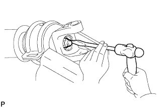
Using a hammer and chisel, loosen the staked part of the nut and remove the nut and washer.
-
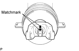
Place matchmarks on the intermediate shaft and center yoke.
-
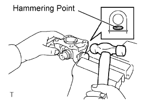
Using a brass bar and hammer, tap out the center yoke.
-
Remove the washer and center support bearing from the intermediate shaft.
-
-
INSPECT CENTER NO. 1 SUPPORT BEARING ASSEMBLY
-
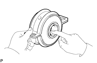
When turning the center bearing with your hand, check that it turns smoothly without catching and that there are no cracks or damage.
If there are any defects, replace it.
If there are any damage to the lip of the center bearing case, replace it.
-
-
INSPECT PROPELLER SHAFT AND INTERMEDIATE SHAFT
-
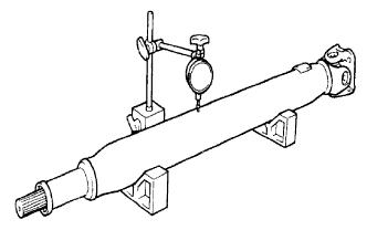
Using a dial indicator, measure the propeller shaft and intermediate shaft runout.
Maximum runout Item Specified Condition Propeller shaft 0.8 mm (0.031 in.) Intermediate shaft 0.8 mm (0.031 in.) If the runout is greater than the maximum, replace the shaft.
-