ELECTRONICALLY CONTROLLED BRAKE SYSTEM(w/o Vacuum Brake Booster) TERMINALS OF ECU
-
TERMINAL INSPECTION
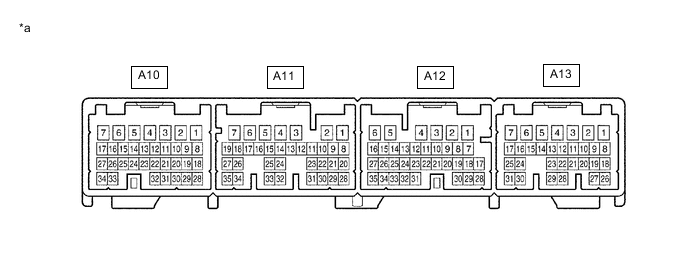
*a Component without harness connected
(Skid Control ECU Assembly)
- -
-
Measure the voltage or resistance between each terminal or between each terminal and body ground.
-
Connect the GTS to the DLC3, and check the communication condition with the skid control ECU assembly.
-
Using an oscilloscope, check the pulse generated between each terminal or between each terminal and body ground.
Note
-
Inspection should be performed from the back of the connector with the connector connected to the skid control ECU assembly.
-
The voltage between the terminals of the brake actuator assembly may become 0 V due to the fail-safe function when the brake warning light / yellow (minor malfunction) comes on (malfunctioning).
Tech Tips
Inspect the skid control ECU assembly from the wire harness side while the connector is connected.
Standard Terminal No. (Symbol) Wiring Color Terminal Description Condition Specified Condition A10-1 (GND) - Body ground W-B - Body ground Skid control ECU assembly ground Engine switch off Below 1 Ω A10-2 - - (Not used) - - A10-3 (BS01) - Body ground G - Body ground Master cut solenoid 1 power supply output Approximately 1.5 seconds after turning engine switch on (IG) 8.8 to 14 V A10-4 (SMC1) - Body ground B - Body ground Master cut solenoid 1 output Brake pedal depressed approximately 1.5 seconds after turning engine switch on (IG) Below 1.5 V A10-5 - - (Not used) - - A10-6 (FRR+) - Body ground Y - Body ground Front reduction linear solenoid RH (+) output Engine switch on (IG), after approximately 1.5 seconds brake pedal depressed → released Pulse generation
(see waveform 1)
A10-7 (FRR-) - Body ground L - Body ground Front reduction linear solenoid RH (-) output Approximately 1.5 seconds after turning engine switch on (IG) Below 1.5 V A10-8 (E) - Body ground W - Body ground Pressure sensor 1 ground Engine switch off Below 1 Ω A10-9 (VCM) - Body ground B - Body ground Pressure sensor 1 power supply output Engine switch on (IG) 4.75 to 5.25 V A10-10 (SG1) - Body ground Shielded - Body ground Pressure sensor 1 shield ground Engine switch off Below 1 Ω A10-11 (MR1) - Body ground V - Body ground ABS motor relay 1 power supply output Approximately 1.5 seconds after turning engine switch on (IG) 8.8 to 14 V A10-12 (SG3) - Body ground Shielded - Body ground Pressure sensor 3 shield ground Engine switch off Below 1 Ω A10-13 - - (Not used) - - A10-14 (CTY) - Body ground Y - Body ground Front door courtesy light switch assembly LH input Driver door closed → open Pulse generation (see waveform 2) → Below 1.5 V A10-15 - - (Not used) - - A10-16 (RLR-) - Body ground Y - Body ground Rear reduction linear solenoid LH (-) output Approximately 1.5 seconds after turning engine switch on (IG) Below 1.5 V A10-17 (RLR+) - Body ground B - Body ground Rear reduction linear solenoid LH (+) output Brake pedal depressed approximately 1.5 seconds after turning engine switch on (IG) Pulse generation
(see waveform 3)
A10-18 (PRL) - Body ground Y - Body ground Rear wheel cylinder pressure sensor LH signal input Engine switch on (IG), brake pedal released 0.3 to 0.7 V A10-19 - - (Not used) - - A10-20 - - (Not used) - - A10-21 (PAC1) - Body ground W - Body ground Accumulator pressure sensor input Engine switch on (IG), after pump motor operates and stops by pedal operation 3 to 4.7 V A10-22 (FR+) - Body ground G - Body ground Front speed sensor RH power supply output Engine switch on (IG) 8 to 14 V A10-23 (FR-) - Body ground R - Body ground Front speed sensor RH input While driving at approximately 30 km/h (19 mph) Pulse generation
(see waveform 4)
A10-24 (R1-) - Body ground B - Body ground ABS motor relay 1 output Engine switch on (IG), pump motor in operation Below 1.5 V A10-25 - - (Not used) - - A10-26 (RLA+) - Body ground R - Body ground Rear addition linear solenoid LH (+) output Brake pedal depressed approximately 1.5 seconds after turning engine switch on (IG) Pulse generation
(see waveform 3)
A10-27 (RLA-) - Body ground G - Body ground Rear addition linear solenoid LH (-) output Approximately 1.5 seconds after turning engine switch on (IG) Below 1.5 V A10-28 - - (Not used) - - A10-29 (MTT) - Body ground V - Body ground ABS motor relay test input Engine switch on (IG), ABS motor relay off → on Below 2 V → 5 V or higher A10-30 (PMC1) - Body ground R - Body ground Master cylinder pressure sensor 1 input Engine switch on (IG), brake pedal released 0.3 to 0.7 V A10-31 (PCK1) - Body ground B - Body ground Pressure sensor 1 stuck check output Engine switch on (IG) Below 1.2 V A10-32 (PFR) - Body ground G - Body ground Front wheel cylinder pressure sensor RH signal input Engine switch on (IG), brake pedal released 0.3 to 0.7 V A10-33 (FRA-) - Body ground W - Body ground Front addition linear solenoid RH (-) output Approximately 1.5 seconds after turning engine switch on (IG) Below 1.5 V A10-34 (FRA+) - Body ground B - Body ground Front addition linear solenoid RH (+) output Brake pedal depressed approximately 1.5 seconds after turning engine switch on (IG) Pulse generation
(see waveform 3)
A11-1 (GND3) - Body ground BR - Body ground Skid control ECU assembly ground 3 Engine switch off Below 1 Ω A11-2 (IG1) - Body ground G - Body ground IG1 power source input Engine switch on (IG) 11 to 14 V A11-3 (GND2) - Body ground W-B - Body ground Skid control ECU assembly ground 2 Engine switch off Below 1 Ω A11-4 (+BI1) - Body ground B - Body ground +B power source 1 Always 11 to 14 V A11-5 (+BI3) - Body ground G - Body ground +B power source 3 Always 11 to 14 V A11-6 (LBL) - Body ground L - Body ground Brake fluid level warning switch (Brake master cylinder reservoir assembly) input Brake fluid level warning switch (Brake master cylinder reservoir assembly) off → on 4 to 8 V → Below 1.5 V A11-7 (CBI1) - Body ground B - Body ground Brake control power supply with bracket assembly 1 power supply input Engine switch on (IG) 8.8 to 14 V A11-8 (CA1H) - Body ground GR - Body ground CAN communication line 1 Check for DTC using the GTS CAN communication DTC is not output A11-9 (CA1L) - Body ground W - Body ground CAN communication line 1 Check for DTC using the GTS CAN communication DTC is not output A11-10 (CA2H) - Body ground L - Body ground CAN communication line 2 Check for DTC using the GTS CAN communication DTC is not output A11-11 (CA2L) - Body ground W - Body ground CAN communication line 2 Check for DTC using the GTS CAN communication DTC is not output A11-12 - - (Not used) - - A11-13 - - (Not used) - - A11-14 (STP2) - Body ground W - Body ground Stop light signal input Stop light switch assembly on → off
(Brake pedal depressed → released)
8 to 14 V → Below 1.5 V A11-15 - - (Not used) - - A11-16 - - (Not used) - - A11-17 - - (Not used) - - A11-18 - - (Not used) - - A11-19 (CSW) - Body ground B - Body ground VSC OFF switch (No. 2 satellite switch set) input VSC OFF switch (No. 2 satellite switch set) held on → off (Released) Below 1 Ω → 10 kΩ or higher A11-20 (ENA) - Body ground V - Body ground Brake control power supply with bracket assembly signal output Approximately 1.5 seconds after turning engine switch on (IG) Pulse generation
(see waveform 5)
A11-21 - - (Not used) - - A11-22 (SP1) - Body ground LG - Body ground Speedometer signal output While driving at approximately 20 km/h (12 mph) Pulse generation
(see waveform 6)
A11-23 - - (Not used) - - A11-24 - - (Not used) - - A11-25 - - (Not used) - - A11-26 - - (Not used) - - A11-27 - - (Not used) - - A11-28 - - (Not used) - - A11-29 - - (Not used) - - A11-30 - - (Not used) - - A11-31 - - (Not used) - - A11-32 - - (Not used) - - A11-33 - - (Not used) - - A11-34 (RL+) - Body ground W - Body ground Rear speed sensor LH power supply output Engine switch on (IG) 8 to 14 V A11-35 (RL-) - Body ground B - Body ground Rear speed sensor LH input While driving at approximately 30 km/h (19 mph) Pulse generation
(see waveform 4)
A12-1 (GND5) - Body ground W-B - Body ground Skid control ECU assembly ground 5 Engine switch off Below 1 Ω A12-2 (CBI2) - Body ground B - Body ground Brake control power supply with bracket assembly 2 power supply input Engine switch on (IG) 8.8 to 14 V A12-3 (GND4) - Body ground W-B - Body ground Skid control ECU assembly ground 4 Engine switch off Below 1 Ω A12-4 (STPO) - Body ground LG - Body ground Stop light signal output Engine switch on (IG) 11 to 14 V A12-5 (IG2) - Body ground B - Body ground IG2 power source input Engine switch on (IG) 11 to 14 V A12-6 - - (Not used) - - A12-7 - - (Not used) - - A12-8 (SKG) - Body ground W - Body ground Brake pedal stroke sensor assembly ground Engine switch off Below 1 Ω A12-9 - - (Not used) - - A12-10 (VCSK) - Body ground B - Body ground Brake pedal stroke sensor assembly power supply output Engine switch on (IG) 4.5 to 5.5 V A12-11 - - (Not used) - - A12-12 - - (Not used) - - A12-13 - - (Not used) - - A12-14 (HZRI) - Body ground SB - Body ground Brake hold switch input Brake hold switch held on → off (Released) Below 1 Ω → 10 kΩ or higher A12-15 - - (Not used) - - A12-16 (STP) - Body ground R - Body ground Stop light switch assembly input Stop light switch assembly on → off
(Brake pedal depressed → released)
8 to 14 V → Below 1.5 V A12-17 - - (Not used) - - A12-18 - - (Not used) - - A12-19 - - (Not used) - - A12-20 (SKS) - Body ground L - Body ground Brake pedal stroke sensor assembly 1 signal input Engine switch on (IG), brake pedal released 0.8 to 1.2 V A12-21 - - (Not used) - - A12-22 (SKS2) - Body ground R - Body ground Brake pedal stroke sensor assembly 2 signal input Engine switch on (IG), brake pedal released 3.8 to 4.2 V A12-23 - - (Not used) - - A12-24 - - (Not used) - - A12-25 - - (Not used) - - A12-26 - - (Not used) - - A12-27 - - (Not used) - - A12-28 - - (Not used) - - A12-29 - - (Not used) - - A12-30 (FAIL) - Body ground L - Body ground Brake control power supply with bracket assembly signal input Approximately 1.5 seconds after turning engine switch on (IG) Pulse generation
(see waveform 7)
A12-31 (FL+) - Body ground B - Body ground Front speed sensor LH power supply output Engine switch on (IG) 8 to 14 V A12-32 (FL-) - Body ground W - Body ground Front speed sensor LH input While driving at approximately 30 km/h (19 mph) Pulse generation
(see waveform 4)
A12-33 - - (Not used) - - A12-34 - - (Not used) - - A12-35 - - (Not used) - - A13-1 (RRR-) - Body ground Y - Body ground Rear reduction linear solenoid RH (-) output Approximately 1.5 seconds after turning engine switch on (IG) Below 1.5 V A13-2 (RRR+) - Body ground L - Body ground Rear reduction linear solenoid RH (+) output Brake pedal depressed approximately 1.5 seconds after turning engine switch on (IG) Pulse generation
(see waveform 3)
A13-3 (GND6) - Body ground W-B - Body ground Skid control ECU assembly ground 6 Engine switch off Below 1 Ω A13-4 (SMC2) - Body ground G - Body ground Master cut solenoid 2 output Brake pedal depressed approximately 1.5 seconds after turning engine switch on (IG) Below 1.5 V A13-5 (+BI2) - Body ground V - Body ground +B power source 2 Always 11 to 14 V A13-6 (+BI4) - Body ground G - Body ground +B power source 4 Always 11 to 14 V A13-7 (BS02) - Body ground B - Body ground Master cut solenoid 2 power supply output Approximately 1.5 seconds after turning engine switch on (IG) 8.8 to 14 V A13-8 (FLR+) - Body ground B - Body ground Front reduction linear solenoid LH (+) output Engine switch on (IG), after approximately 1.5 seconds brake pedal depressed → released Pulse generation
(see waveform 1)
A13-9 (FLR-) - Body ground W - Body ground Front reduction linear solenoid LH (-) output Approximately 1.5 seconds after turning engine switch on (IG) Below 1.5 V A13-10 (SG2) - Body ground Shielded - Body ground Pressure sensor 2 shield ground Engine switch off Below 1 Ω A13-11 (EXO) - Body ground B - Body ground No. 3 Semiconductor Power integration ECU output Engine switch on (IG) 11 to 14 V A13-12 - - (Not used) - - A13-13 - - (Not used) - - A13-14 (R2-) - Body ground P - Body ground ABS motor relay 2 output Engine switch on (IG), pump motor in operation Below 1.5 V A13-15 (E2) - Body ground L - Body ground Pressure sensor 2 ground Engine switch off Below 1 Ω A13-16 (VCM2) - Body ground W - Body ground Pressure sensor 2 power supply output Engine switch on (IG) 4.75 to 5.25 V A13-17 (MR2) - Body ground GR - Body ground ABS motor relay 2 power supply output Approximately 1.5 seconds after turning engine switch on (IG) 8.8 to 14 V A13-18 (FLA-) - Body ground Y - Body ground Front addition linear solenoid LH (-) output Approximately 1.5 seconds after turning engine switch on (IG) Below 1.5 V A13-19 (FLA+) - Body ground B - Body ground Front addition linear solenoid LH (+) output Brake pedal depressed approximately 1.5 seconds after turning engine switch on (IG) Pulse generation
(see waveform 3)
A13-20 - - (Not used) - - A13-21 (RR-) - Body ground B - Body ground Rear speed sensor RH input While driving at approximately 30 km/h (19 mph) Pulse generation
(see waveform 4)
A13-22 (RR+) - Body ground W - Body ground Rear speed sensor RH power supply output Engine switch on (IG) 8 to 14 V A13-23 (PFL) - Body ground B - Body ground Front wheel cylinder pressure sensor LH signal input Engine switch on (IG), brake pedal released 0.3 to 0.7 V A13-24 (PRR) - Body ground R - Body ground Rear wheel cylinder pressure sensor RH signal input Engine switch on (IG), brake pedal released 0.3 to 0.7 V A13-25 - - (Not used) - - A13-26 (RRA+) - Body ground R - Body ground Rear addition linear solenoid RH (+) output Brake pedal depressed approximately 1.5 seconds after turning engine switch on (IG) Pulse generation
(see waveform 3)
A13-27 (RRA-) - Body ground W - Body ground Rear addition linear solenoid RH (-) output Approximately 1.5 seconds after turning engine switch on (IG) Below 1.5 V A13-28 (PMC2) - Body ground Y - Body ground Master cylinder pressure sensor 2 input Engine switch on (IG), brake pedal released 0.3 to 0.7 V A13-29 (PCK2) - Body ground G - Body ground Pressure sensor 2 stuck check output Engine switch on (IG) Below 1.2 V A13-30 - - (Not used) - - A13-31 - - (Not used) - - -
-
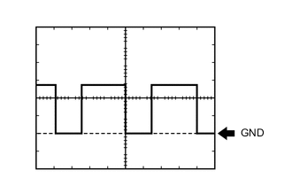
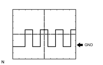
Waveform 1 (Reference)
Item Content Tester Connection A10-6 (FRR+) - Body ground
A13-8 (FLR+) - Body ground
Tool Setting 5 V/DIV., 50 ms./DIV. Vehicle Condition Engine switch on (IG), after approximately 1.5 seconds brake pedal depressed → released Tech Tips
Normal waveform is output only when +BI voltage is normal (11 to 14 V).
-
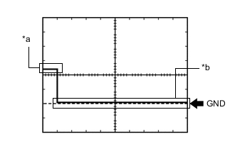
*a Driver door closed *b Driver door open Waveform 2 (Reference)
Item Content Tester Connection A10-14 (CTY) - Body ground Tool Setting 5 V/DIV., 10 ms./DIV. Vehicle Condition Driver door closed → open -

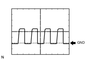
Waveform 3 (Reference)
Item Content Tester Connection A10-17 (RLR+) - Body ground
A10-26 (RLA+) - Body ground
A10-34 (FRA+) - Body ground
A13-2 (RRR+) - Body ground
A13-19 (FLA+) - Body ground
A13-26 (RRA+) - Body ground
Tool Setting 5 V/DIV., 50 ms./DIV. Vehicle Condition Brake pedal depressed approximately 1.5 seconds after turning engine switch on (IG) Tech Tips
Normal waveform is output only when +BI voltage is normal (11 to 14 V).
-
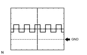
Waveform 4 (Reference)
Item Content Tester Connection A10-23 (FR-) - Body ground
A11-35 (RL-) - Body ground
A12-32 (FL-) - Body ground
A13-21 (RR-) - Body ground
Tool Setting 0.5 V/DIV., 2 ms./DIV. Vehicle Condition While driving at approximately 30 km/h (19 mph) -
Waveform 5 (Reference)
Item Content Tester Connection A11-20 (ENA) - Body ground Tool Setting 2 V/DIV., 50 ms./DIV. Vehicle Condition Approximately 1.5 seconds after turning engine switch on (IG) -
Waveform 6 (Reference)
Item Content Tester Connection A11-22 (SP1) - Body ground Tool Setting 5 V/DIV., 50 ms./DIV. Vehicle Condition While driving at approximately 20 km/h (12 mph) -

Waveform 7 (Reference)
Item Content Tester Connection A12-30 (FAIL) - Body ground Tool Setting 5 V/DIV., 200 ms./DIV. Vehicle Condition Approximately 1.5 seconds after turning engine switch on (IG)
-