RADIATOR INSTALLATION
CAUTION / NOTICE / HINT
Tech Tips
-
Use the same procedure for RHD and LHD vehicles.
-
The procedure listed below is for LHD vehicles.
PROCEDURE
-
INSTALL LOWER RADIATOR SUPPORT
-
Install the 2 lower radiator supports to the radiator assembly.
-
-
INSTALL SUB-RADIATOR SUPPORT CUSHION
-
Install the 2 sub-radiator support cushions to the radiator assembly.
-
-
INSTALL FAN WITH MOTOR ASSEMBLY
-
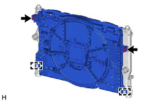
Attach the guide.
-
Install the fan with motor assembly to the radiator assembly with the 2 bolts.
Note
Do not damage the radiator assembly when installing the fan with motor assembly.
- Torque:
- 12 N*m { 122 kgf*cm, 9 ft.*lbf }
-
-
INSTALL NO. 5 RADIATOR TO SUPPORT SEAL
-
Install a new No. 5 radiator support to seal to the radiator assembly.
-
-
INSTALL NO. 4 RADIATOR TO SUPPORT SEAL
-
Install a new No. 4 radiator support to seal to the radiator assembly.
-
-
INSTALL NO. 3 RADIATOR TO SUPPORT SEAL
-
Install a new No. 3 radiator support to seal to the radiator assembly.
-
-
INSTALL NO. 2 RADIATOR TO SUPPORT SEAL
-
Install a new No. 2 radiator support to seal to the radiator assembly.
-
-
INSTALL NO. 1 RADIATOR TO SUPPORT SEAL
-
Upper Side:
-
Install a new No. 1 radiator support to seal to the radiator assembly.
-
-
Lower Side:
-
Install a new No. 1 radiator support to seal to the radiator assembly.
-
-
-
INSTALL REAR RADIATOR SIDE AIR GUIDE PLATE RH
-
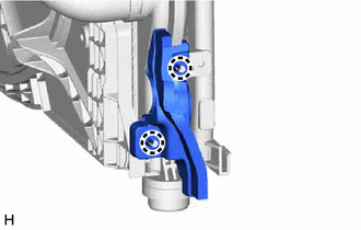
Attach the claw to install the rear radiator side air guide plate RH to the radiator assembly.
-
-
INSTALL NO. 2 RADIATOR HOSE
-
Install the No. 2 radiator hose to the radiator assembly, and slide the clip to secure the hose.
Note
Install so that the No. 2 radiator hose paint mark and radiator assembly positioning stopper are securely overlapped. (Rotational Direction)
-
Attach the clamp to install the No. 2 radiator hose with the No. 4 radiator hose and water inlet hose.
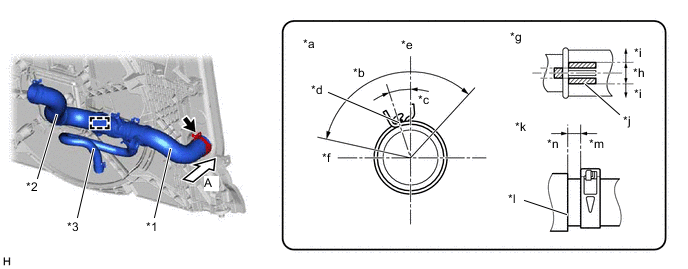
*1 No. 2 Radiator Hose *2 No. 4 Radiator Hose *3 Water Inlet Hose - - *a View A *b 120° *c 18° *d Paint Mark *e Upper Side *f LH Side *g Rotational Direction *h OK *i NG *j Variation Range *k Axis Direction *l Stopper *m 2 to 5 mm (0.0787 to 0.197 in.) *n 0 to 1 mm (0 to 0.0394 in.)
-
-
INSTALL NO. 1 RADIATOR HOSE
-
Install the No. 1 radiator hose to the radiator assembly, and slide the clip to secure the hose.
Note
Install so that the No. 1 radiator hose paint mark and radiator assembly positioning stopper are securely overlapped. (Rotational Direction)
-
Attach the clamps to install the No. 1 radiator hose with the No. 3 radiator hose.
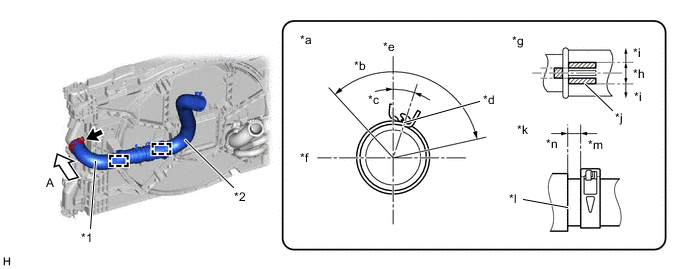
*1 No. 1 Radiator Hose *2 No. 3 Radiator Hose *a View A *b 120° *c 18° *d Paint Mark *e Upper Side *f LH Side *g Rotational Direction *h OK *i NG *j Variation Range *k Axis Direction *l Stopper *m 2 to 5 mm (0.0787 to 0.197 in.) *n 0 to 1 mm (0 to 0.0394 in.)
-
-
INSTALL INTERCOOLER COOLING RADIATOR ASSEMBLY
-
INSTALL INTERCOOLER COOLING WATER HOSE ASSEMBLY
-
Connect the intercooler water hose assembly, and slide the clips to secure the hose to the intercooler cooling radiator assembly.
Note
-
Install so that the intercooler water hose assembly paint mark and intercooler cooling radiator assembly positioning stopper are securely overlapped. (Rotational Direction)
-
Make sure the intercooler water hose assembly is securely inserted to the stopper. (Axial Direction)
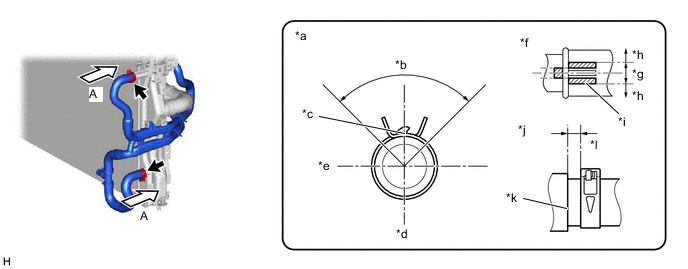
*a View A *b 90° *c Paint Mark *d Lower Side *e RH Side *f Rotational Direction *g OK *h NG *i Variation Range *j Axis Direction *k Stopper *l 2 to 7 mm (0.0787 to 0.276 in.) -
-
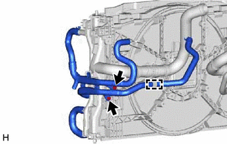
Install the intercooler water hose assembly with the 2 bolts.
- Torque:
- 8.0 N*m { 82 kgf*cm, 71 in.*lbf }
-
Attach the clamp.
-
-
INSTALL DISCHARGE HOSE SUB-ASSEMBLY
-
Attach the clamp to install the discharge hose sub-assembly to the fan with motor assembly.
-
-
INSTALL REAR RADIATOR SIDE AIR GUIDE PLATE LH
-
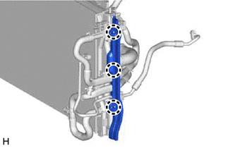
Attach the claw and install the rear radiator side air guide plate LH to the radiator assembly.
-
-
INSTALL RADIATOR ASSEMBLY
-
Install the radiator assembly together with the intercooler cooling radiator assembly and fan with motor assembly to the vehicle.
Note
-
Perform the following procedure with 2 or more people to prevent damage to the radiator assembly.
-
Do not damage the radiator assembly, fan with motor assembly, cooler pipe or cooling hoses when installing them.
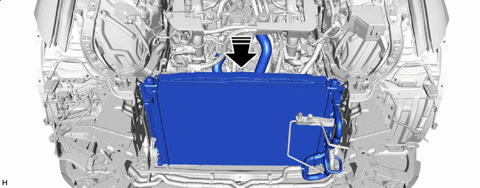

Install in this Direction - - -
-
-
INSTALL NO. 1 RADIATOR AIR GUIDE LH
-
Install the No. 1 radiator air guide LH with the 5 clips.
-
-
INSTALL NO. 1 RADIATOR AIR GUIDE RH
-
Install the No. 1 radiator air guide RH with the 5 clips.
-
-
INSTALL COOLER CONDENSER ASSEMBLY
-
Insert the cooler condenser assembly into the vehicle and attach the guide.
Note
When inserting the cooler condenser assembly, do not damage the cooler condenser assembly and radiator assembly.
-
Attach the claw to install the cooler condenser assembly.
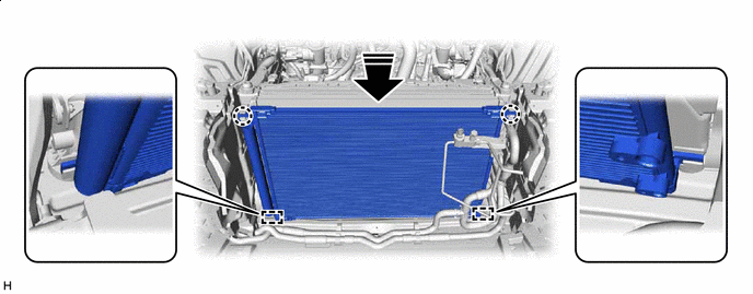
Install in this Direction - -
-
-
CONNECT DISCHARGE HOSE SUB-ASSEMBLY
-
Compressor with Pulley Assembly Side: (for 2WD)
-
Compressor with Pulley Assembly Side: (for AWD)
-
Cooler Condenser Assembly Side:
-
-
CONNECT LIQUID TUBE SUB-ASSEMBLY A
-
CONNECT NO. 2 INTERCOOLER COOLING WATER HOSE
-
Connect the No. 2 intercooler cooling water hose, and slide the clips to secure the hose to the intercooler cooler water hose assembly.
Note
-
Install so that the No. 2 intercooler cooling water hose paint mark and intercooler cooler water hose assembly positioning stopper are securely overlapped. (Rotational Direction)
-
Make sure the No. 2 intercooler cooling water hose is securely inserted to the stopper. (Axial Direction)
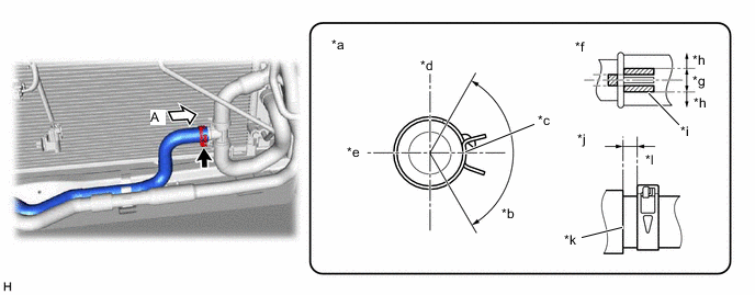
*a View A *b 120° *c Paint Mark *d Upper Side *e Rear Side *f Rotational Direction *g OK *h NG *i Variation Range *j Axis Direction *k Stopper *l 2 to 7 mm (0.0787 to 0.276 in.) -
-
-
CONNECT NO. 1 INTERCOOLER COOLING WATER HOSE
-
Connect the No. 1 intercooler cooling water hose, and slide the clips to secure the hose to the intercooler cooler water hose assembly.
Note
-
Install so that the No. 1 intercooler cooling water hose paint mark and intercooler cooler water hose assembly positioning stopper are securely overlapped. (Rotational Direction)
-
Make sure the No. 1 intercooler cooling water hose is securely inserted to the stopper. (Axial Direction)
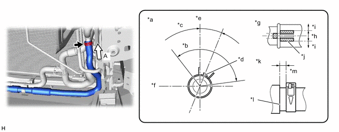
*a View A *b 120° *c 22.6° *d Paint Mark *e Front Side *f RH Side *g Rotational Direction *h OK *i NG *j Variation Range *k Axis Direction *l Stopper *m 2 to 7 mm (0.0787 to 0.276 in.) - - -
-
-
INSTALL UPPER RADIATOR SUPPORT SUB-ASSEMBLY
-
Install the upper radiator support sub-assembly with the 4 bolts.
- Torque:
- 12.5 N*m { 127 kgf*cm, 9 ft.*lbf }
-
-
INSTALL HOOD LOCK CONTROL CABLE COVER LH (for LHD)
-
Attach the clamp to connect the hood lock control cable cover LH.
-
Install the screw.
-
-
INSTALL HOOD LOCK CONTROL CABLE COVER RH
-
Attach the clamp to connect the hood lock control cable cover RH.
-
Install the screw.
-
-
CONNECT ENGINE ROOM MAIN WIRE
-
Attach the clamps to connect the engine room main wire.
-
Connect the connector.
-
-
INSTALL HOOD LOCK SUPPORT BRACE
-
Install the hood lock support brace with the 2 bolts.
- Torque:
- 12.5 N*m { 127 kgf*cm, 9 ft.*lbf }
-
Attach the clamps.
-
-
CONNECT INTERCOOLER COOLING WATER OUTLET HOSE
-
Connect the intercooler cooling water outlet hose, and slide the clips to secure the hose to the water tube.
Note
-
Install so that the intercooler cooling water outlet hose paint mark and water tube positioning stopper are securely overlapped. (Rotational Direction)
-
Make sure the intercooler cooling water outlet hose is securely inserted to the stopper. (Axial Direction)
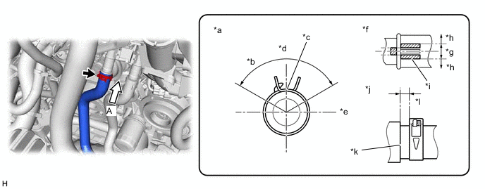
*a View A *b 120° *c Paint Mark *d Front Side *e LH Side *f Rotational Direction *g OK *h NG *i Variation Range *j Axis Direction *k Stopper *l 2 to 7 mm (0.0787 to 0.276 in.) -
-
-
CONNECT WATER INLET HOSE
-
Connect the water inlet hose, and slide the clips to secure the hose to the water tube.
Note
-
Install so that the water inlet hose paint mark and oil cooler assembly positioning stopper are securely overlapped. (Rotational Direction)
-
Make sure the water inlet hose is securely inserted to the stopper. (Axial Direction)
-
-
Attach the clamp.
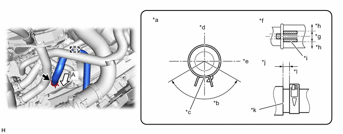
*a View A *b 120° *c Paint Mark *d Rear Side *e LH Side *f Rotational Direction *g OK *h NG *i Variation Range *j Axis Direction *k Stopper *l 2 to 7 mm (0.0787 to 0.276 in.)
-
-
CONNECT NO. 4 RADIATOR HOSE
-
Connect the No. 4 radiator hose to the water inlet assembly, and slide the clip to secure the hose.
Note
Install so that the No. 4 radiator hose paint mark and water inlet assembly positioning stopper are securely overlapped. (Rotational Direction)
-
Attach the clamp.

*a View A *b 120° *c 45.4° *d Paint Mark *e Upper Side *f RH Side *g Rotational Direction *h OK *i NG *j Variation Range *k Axis Direction *l Stopper *m 2 to 6 mm (0.0787 to 0.236 in.) *n 0 to 1 mm (0 to 0.0394 in.)
-
-
CONNECT NO. 3 RADIATOR HOSE
-
Connect the No. 3 radiator hose to the water control valve, and slide the clip to secure the hose.
Note
Install so that the No. 3 radiator hose paint mark and water control valve positioning stopper are securely overlapped. (Rotational Direction)
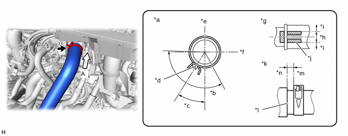
*a View A *b 120° *c 32.1° *d Paint Mark *e Upper Side *f LH Side *g Rotational Direction *h OK *i NG *j Variation Range *k Axis Direction *l Stopper *m 2 to 6 mm (0.0787 to 0.236 in.) *n 0 to 1 mm (0 to 0.0394 in.)
-
-
CONNECT NO. 3 TRANSMISSION OIL COOLER HOSE (w/ In-tank Oil Cooler)
-
Connect the No. 3 transmission oil cooler hose to the radiator assembly, and slide the clip to secure the hose.
-
Attach the clamp.
-
-
CONNECT NO. 1 OIL COOLER OUTLET HOSE (w/ In-tank Oil Cooler)
-
Connect the No. 1 oil cooler outlet hose to the radiator assembly, and slide the clip to secure the hose.
-
Attach the clamp.
-
-
INSTALL INTERCOOLER RESERVE TANK ASSEMBLY
-
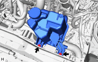
Install the intercooler reserve tank assembly to the fan with motor assembly with the 2 bolts.
- Torque:
- 5.0 N*m { 51 kgf*cm, 44 in.*lbf }
-
for 2WD:
-
Connect the water by-pass hose to the electric water pump assembly, and slide the clip to secure the hose.
Note
-
Install so that the water by-pass hose paint mark and electric water pump assembly positioning stopper are securely overlapped. (Rotational Direction)
-
Make sure the water by-pass hose is securely inserted to the stopper. (Axial Direction)
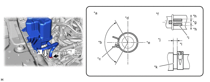
*1 Water By-pass Hose - - *a View A *b 120° *c Paint Mark *d Front Side *e RH Side *f Rotational Direction *g OK *h NG *i Variation Range *j Axis Direction *k Stopper *l 2 to 7 mm (0.0787 to 0.276 in.) -
-
-
for AWD:
-
Connect the water by-pass hose to the electric water pump assembly, and slide the clip to secure the hose.
Note
-
Install so that the water by-pass hose paint mark and electric water pump assembly positioning stopper are securely overlapped. (Rotational Direction)
-
Make sure the water by-pass hose is securely inserted to the stopper. (Axial Direction)
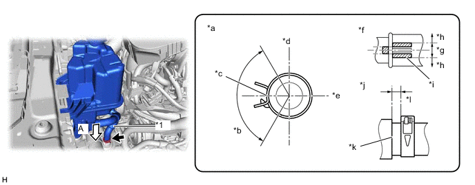
*1 Water By-pass Hose - - *a View A *b 120° *c Paint Mark *d Front Side *e RH Side *f Rotational Direction *g OK *h NG *i Variation Range *j Axis Direction *k Stopper *l 2 to 7 mm (0.0787 to 0.276 in.) -
-
-
Connect the intercooler reserve tank hose, and slide the clips to secure the hose to the intercooler reserve tank assembly.
Note
-
Install so that the intercooler reserve tank hose paint mark and intercooler reserve tank assembly positioning stopper are securely overlapped. (Rotational Direction)
-
Make sure the intercooler reserve tank hose is securely inserted to the stopper. (Axial Direction)
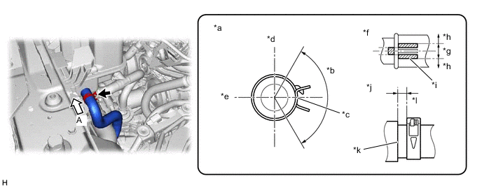
*a View A *b 120° *c Paint Mark *d Upper Side *e Front Side *f Rotational Direction *g OK *h NG *i Variation Range *j Axis Direction *k Stopper *l 2 to 7 mm (0.0787 to 0.276 in.) -
-
-
INSTALL RADIATOR RESERVE TANK ASSEMBLY
-
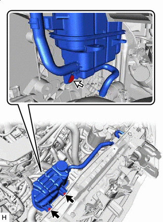

Bolt 
Clip Install the radiator reserve tank assembly to the fan with motor assembly with the 2 bolts and clip.
- Torque:
- 5.0 N*m { 51 kgf*cm, 44 in.*lbf }
-
Connect the reserve tank outlet hose, and slide the clip to secure the hose to the radiator pipe.
Note
-
Install so that the reserve tank outlet hose paint mark and radiator pipe positioning stopper are securely overlapped.
-
Make sure the reserve tank outlet hose is securely inserted to the stopper. (Axial Direction)
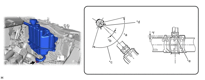
*1 Radiator Pipe - - *a 120° or less *b 14.5° *c Fit the claw of the clip in the following range. *d Paint Mark *e Stopper *f 2 to 5 mm (0.0787 to 0.197 in.) -
-
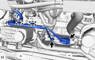
Connect the connectors and attach the clamps.
-
Connect the radiator reserve tank hose, and slide the clip to secure the hose to the radiator assembly.
Note
-
Install so that the radiator reserve tank hose paint mark and radiator assembly positioning stopper are securely overlapped. (Rotational Direction)
-
Make sure the radiator reserve tank hose is securely inserted to the stopper. (Axial Direction)
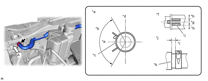
*a View A *b 120° *c Paint Mark *d Upper Side *e LH Side *f Rotational Direction *g OK *h NG *i Variation Range *j Axis Direction *k Stopper *l 2 to 7 mm (0.0787 to 0.276 in.) -
-
-
INSTALL HIGH PITCHED HORN ASSEMBLY
-
INSTALL LOW PITCHED HORN ASSEMBLY
-
INSTALL HOOD LOCK ASSEMBLY
-
INSTALL HOOD LOCK RELEASE LEVER PROTECTOR
-
INSTALL AIR CLEANER SUPPORT BRACKET
-
CONNECT NO. 3 ENGINE ROOM WIRE
-
INSTALL FRONT BUMPER NO. 2 REINFORCEMENT SUB-ASSEMBLY
-
INSTALL FRONT BUMPER REINFORCEMENT SUB-ASSEMBLY
-
INSTALL HEADLIGHT ASSEMBLY LH
-
INSTALL HEADLIGHT ASSEMBLY RH
Tech Tips
Use the same procedure described for the LH side.
-
INSTALL FRONT BUMPER ENERGY ABSORBER SUB-ASSEMBLY
-
INSTALL LOWER ARM BRACKET BRACE SUB-ASSEMBLY LH
-
INSTALL LOWER ARM BRACKET BRACE SUB-ASSEMBLY RH
-
INSTALL AIR CLEANER ASSEMBLY LH
-
INSTALL AIR CLEANER ASSEMBLY RH
-
INSTALL RADIATOR SUPPORT TO CROSSMEMBER BRACE SUB-ASSEMBLY LH
-
INSTALL RADIATOR SUPPORT TO CROSSMEMBER BRACE SUB-ASSEMBLY RH
-
INSTALL FRONT BUMPER
-
for Sport Package:
-
except Sport Package:
-
-
ADD ENGINE COOLANT
-
ADD COOLANT (for Intercooler)
-
CHARGE AIR CONDITIONING SYSTEM WITH REFRIGERANT
-
for HFC-134a (R134a):
-
for HFO-1234yf (R1234yf):
-
-
INSPECT FOR COOLANT LEAK
-
INSPECT FOR COOLANT LEAK (for Intercooler)
-
INSTALL LOWER RADIATOR AIR DEFLECTOR
-
INSTALL UPPER RADIATOR SUPPORT SEAL
-
INSTALL RADIATOR COVER PLATE
-
INSTALL V-BANK COVER SUB-ASSEMBLY
-
INSTALL STRUT BAR BRACKET SUPPORT SUB-ASSEMBLY (for AWD)
-
INSTALL FRONT SUSPENSION MEMBER BRACE (for AWD)
-
INSTALL OIL PAN PROTECTOR (for 2WD)
-
INSTALL NO. 1 ENGINE UNDER COVER ASSEMBLY
-
for 2WD:
-
for AWD:
-
-
INSPECT FOR COOLING FAN MOTOR
-
ADJUST HEADLIGHT AIMING