ECD SYSTEM(w/o Gear Shift Indicator), Diagnostic DTC:P0617
| DTC Code | DTC Name |
|---|---|
| P0617 | Starter Relay Circuit High |
DESCRIPTION
While the engine is being cranked, positive battery voltage is applied to terminal STA of the ECM.
If the ECM detects the starter control (STA) signal while the vehicle is being driven, it determines that there is a malfunction in the STA circuit. The ECM then illuminates the MIL and stores the DTC.
This monitor runs when the vehicle has been driven at 20 km/h (12.5 mph) or more for more than 20 seconds.
| DTC Detection Drive Pattern | DTC Detection Condition | Trouble Area |
|---|---|---|
| Drive vehicle for 25 seconds or more at a speed of 20 km/h (12.5 mph) or more and an engine speed of 1000 rpm or more | Conditions (a), (b) and (c) are met for 20 seconds (a) Vehicle speed is more than 20 km/h (12.5 mph). (b) Engine speed is more than 1000 rpm. (c) STA signal is on. (1 trip detection logic) |
|
| DTC No. | Data List |
|---|---|
| P0617 | Starter Signal |
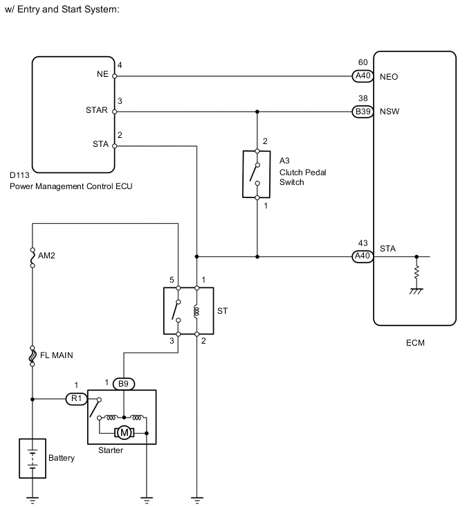
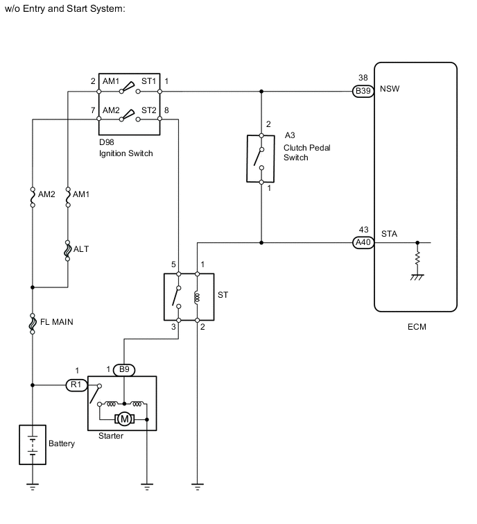
WIRING DIAGRAM
CAUTION / NOTICE / HINT
Note
After replacing the ECM, the new ECM needs registration (See page ) and initialization Click here.
Tech Tips
-
The following troubleshooting process is based on the premise that the engine can crank normally. If the engine does not crank, proceed to the Problem Symptoms Table Click here.
-
If this DTC is output, inspect the starter.
PROCEDURE
-
CHECK IF VEHICLE IS EQUIPPED WITH ENTRY AND START SYSTEM
-
Check if the vehicle is equipped with the entry and start system.
Result Result Proceed to w/o Entry and Start System A w/ Entry and Start System B
B 
READ VALUE USING INTELLIGENT TESTER (STARTER SIGNAL) Click here
A 
-
-
READ VALUE USING INTELLIGENT TESTER (STARTER SIGNAL)
-
Connect the intelligent tester to the DLC3.
-
Turn the ignition switch to ON and turn the tester on.
-
Enter the following menus: Powertrain / Engine and ECT / Data List / Starter Signal.
-
Read the value displayed on the tester when the ignition switch is turned to ON and when the engine is started.
OK Ignition Switch Condition Starter Signal ON OFF Engine Start ON
OK
CONFIRM WHETHER DTC OUTPUT RECURS Click here
NG
-
-
INSPECT IGNITION SWITCH
-
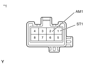
Text in Illustration *1 Component without harness connected
(Ignition Switch)
Disconnect the ignition switch assembly connector.
-
Measure the resistance according to the value(s) in the table below.
Standard Resistance Tester Connection Ignition Switch Position Specified Condition All terminals Off 10 kΩ or higher 2 (AM1) - 1 (ST1) START Below 1 Ω -
Reconnect the ignition switch assembly connector.
NG
REPLACE IGNITION SWITCH ASSEMBLY Click here
OK
-
-
CHECK HARNESS AND CONNECTOR (IGNITION SWITCH ASSEMBLY - CLUTCH PEDAL SWITCH ASSEMBLY)
-
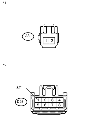
Text in Illustration *1 Front view of wire harness connector
(to Clutch Pedal Switch)
*2 Front view of wire harness connector
(to Ignition Switch)
Disconnect the clutch pedal switch assembly connector.
-
Disconnect the ignition switch assembly connector.
-
Measure the resistance according to the value(s) in the table below.
Standard Resistance Tester Connection Condition Specified Condition A3-2 or D98-1 (ST1) - Body ground Always 10 kΩ or higher -
Reconnect the clutch pedal switch assembly connector.
-
Reconnect the ignition switch assembly connector.
NG
REPAIR OR REPLACE HARNESS OR CONNECTOR Click here
OK
-
-
CHECK HARNESS AND CONNECTOR (CLUTCH PEDAL SWITCH ASSEMBLY - ST RELAY)
-
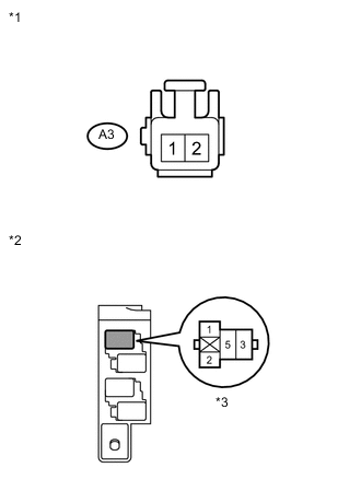
Text in Illustration *1 Front view of wire harness connector
(to Clutch Pedal Switch)
*2 No. 1 Relay Block *3 ST Relay Disconnect the clutch pedal switch assembly connector.
-
Remove the ST relay from the No. 1 relay block.
-
Measure the resistance according to the value(s) in the table below.
Standard Resistance Tester Connection Condition Specified Condition ST relay terminal 1 or A3-1 - Body ground Always 10 kΩ or higher -
Reconnect the clutch pedal switch assembly connector.
-
Reinstall the ST relay.
NG
REPAIR OR REPLACE HARNESS OR CONNECTOR Click here
OK
-
-
CHECK HARNESS AND CONNECTOR (CLUTCH PEDAL SWITCH ASSEMBLY - ECM)
-
Disconnect the ECM connector.
-
Disconnect the clutch pedal switch assembly connector.
-
Measure the resistance according to the value(s) in the table below.
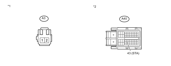
Standard Resistance Tester Connection Condition Specified Condition A3-1 or A40-43 (STA) - Body ground Always 10 kΩ or higher Text in Illustration *1 Front view of wire harness connector
(to Clutch Pedal Switch)
*2 Front view of wire harness connector
(to ECM)
-
Reconnect the ECM connector.
-
Reconnect the clutch pedal switch assembly connector.
OK
INSPECT CLUTCH PEDAL SWITCH ASSEMBLY Click here
NG
REPAIR OR REPLACE HARNESS OR CONNECTOR Click here
-
-
READ VALUE USING INTELLIGENT TESTER (STARTER SIGNAL)
-
Connect the intelligent tester to the DLC3.
-
Turn the ignition switch to ON and turn the tester on.
-
Enter the following menus: Powertrain / Engine and ECT / Data List / Starter Signal.
-
Read the value displayed on the tester when the ignition switch is turned to ON.
OK Switch Condition Starter Signal Ignition switch ON OFF
OK
CONFIRM WHETHER DTC OUTPUT RECURS Click here
NG
-
-
CHECK HARNESS AND CONNECTOR (CLUTCH PEDAL SWITCH ASSEMBLY - POWER MANAGEMENT CONTROL ECU)
-
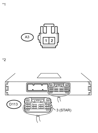
Text in Illustration *1 Front view of wire harness connector
(to Clutch Pedal Switch)
*2 Rear view of wire harness connector
(to Power Management Control ECU)
Disconnect the clutch pedal switch assembly connector.
-
Disconnect the power management control ECU connector.
-
Measure the resistance according to the value(s) in the table below.
Standard Resistance Tester Connection Condition Specified Condition A3-2 or D113-3 (STAR) - Body ground Always 10 kΩ or higher -
Reconnect the clutch pedal switch assembly connector.
-
Reconnect the power management control ECU connector.
NG
REPAIR OR REPLACE HARNESS OR CONNECTOR Click here
OK
-
-
CHECK HARNESS AND CONNECTOR (CLUTCH PEDAL SWITCH ASSEMBLY - ST RELAY)
-
Text in Illustration *1 Front view of wire harness connector
(to Clutch Pedal Switch)
*2 No. 1 Relay Block *3 ST Relay Remove the ST relay from the No. 1 relay block.
-
Disconnect the clutch pedal switch assembly connector.
-
Measure the resistance according to the value(s) in the table below.
Standard Resistance Tester Connection Condition Specified Condition ST relay terminal 1 or A3-1 - Body ground Always 10 kΩ or higher -
Reinstall the ST relay.
-
Reconnect the clutch pedal switch assembly connector.
NG
REPAIR OR REPLACE HARNESS OR CONNECTOR Click here
OK
-
-
CHECK HARNESS AND CONNECTOR (CLUTCH PEDAL SWITCH ASSEMBLY - ECM)
-
Disconnect the ECM connector.
-
Disconnect the clutch pedal switch assembly connector.
-
Measure the resistance according to the value(s) in the table below.
Standard Resistance Tester Connection Condition Specified Condition A40-43 (STA) or A3-1 - Body ground Always 10 kΩ or higher Text in Illustration *1 Front view of wire harness connector
(to Clutch Pedal Switch)
*2 Front view of wire harness connector
(to ECM)
-
Reinstall the ECM connector.
-
Reconnect the clutch pedal switch assembly connector.
NG
REPAIR OR REPLACE HARNESS OR CONNECTOR Click here
OK
-
-
INSPECT CLUTCH PEDAL SWITCH ASSEMBLY
-
Inspect the clutch pedal switch assembly Click here.
NG
REPLACE CLUTCH PEDAL SWITCH ASSEMBLY Click here
OK
-
-
REPLACE ECM
-
Replace the ECM Click here.
NEXT
CONFIRM WHETHER DTC OUTPUT RECURS Click here
-
-
REPLACE IGNITION SWITCH ASSEMBLY
-
Replace the ignition switch assembly Click here.
NEXT
CONFIRM WHETHER DTC OUTPUT RECURS Click here
-
-
REPLACE CLUTCH PEDAL SWITCH ASSEMBLY
-
Replace the clutch pedal switch assembly Click here.
NEXT
CONFIRM WHETHER DTC OUTPUT RECURS Click here
-
-
REPAIR OR REPLACE HARNESS OR CONNECTOR
-
Repair or replace the harness or connector.
NEXT
-
-
CONFIRM WHETHER DTC OUTPUT RECURS
-
Connect the intelligent tester to the DLC3.
-
Clear the DTCs Click here.
-
Turn the ignition switch off.
-
Turn the ignition switch to ON.
-
Drive vehicle for 25 seconds or more at a speed of 20 km/h (12.5 mph) or more and an engine speed of 1000 rpm or more.
-
Confirm that the DTC is not output again.
NEXT 
END
-