AIR CONDITIONING UNIT REASSEMBLY
PROCEDURE
-
INSTALL COVER PLATE
-
Install the cover plate.
-
-
INSTALL COOLER UNIT CASE PACKING (for Automatic Air Conditioning System)
-
Install the cooler unit case packing.
-
-
INSTALL COOLER UNIT CASE PACKING (for Manual Air Conditioning System)
Tech Tips
Use the same procedure as for the automatic air conditioning system.
-
INSTALL COOLER BLOWER CASE
-
Install the cooler blower case from the lower heater case.
-
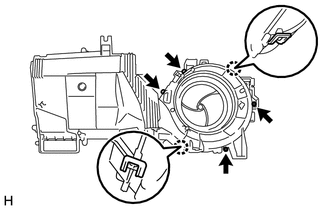
Engage the 2 claws.
-
Install the blower case assembly with the 4 screws.
-
-
INSTALL BLOWER MOTOR CONTROL (for Automatic Air Conditioning System)
-
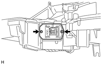
Install the blower motor control with the 2 screws.
-
-
INSTALL BLOWER RESISTOR (for Manual Air Conditioning System)
Tech Tips
Use the same procedure as for the automatic air conditioning system.
-
INSTALL BLOWER RESISTOR (w/o Air Conditioning System)
Tech Tips
Use the same procedure as for the automatic air conditioning system.
-
INSTALL AIR CONDITIONER TUBE ASSEMBLY (for Automatic Air Conditioning System)
-
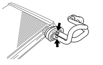
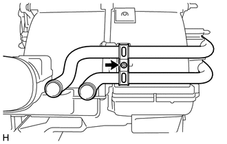
Using a 4 mm hexagon wrench, install the air conditioner tube assembly with the 2 hexagon bolts.
- Torque:
- 3.5 N*m { 36 kgf*cm, 31 in.*lbf }
-
-
INSTALL AIR CONDITIONER TUBE ASSEMBLY (for Manual Air Conditioning System)
Tech Tips
Use the same procedure as for the automatic air conditioning system.
-
INSTALL NO. 1 COOLER THERMISTOR (for Automatic Air Conditioning System)
-
INSTALL NO. 1 COOLER THERMISTOR (for Manual Air Conditioning System)
Tech Tips
Use the same procedure as for the automatic air conditioning system.
-
INSTALL COVER PLATE (w/o Air Conditioning System)
-
Install the cover plate.
-
-
INSTALL NO. 1 COOLER EVAPORATOR SUB-ASSEMBLY (for Automatic Air Conditioning System)
-
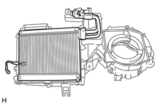
Install the No. 1 cooler evaporator sub-assembly with evaporator pipe as a unit.
-
-
INSTALL NO. 1 COOLER EVAPORATOR SUB-ASSEMBLY (for Manual Air Conditioning System)
Tech Tips
Use the same procedure as for the automatic air conditioning system.
-
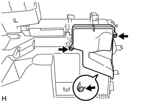
INSTALL COOLING UNIT CASE SUB-ASSEMBLY (for Automatic Air Conditioning System)
-
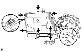
Engage the 2 claws.
-
Install the cooling unit case sub-assembly with the 7 screws.
-
Engage the clamp.
-
-
INSTALL COOLING UNIT CASE SUB-ASSEMBLY (for Manual Air Conditioning System)
Tech Tips
Use the same procedure as for the automatic air conditioning system.
-
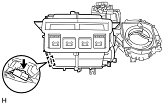
INSTALL COOLING UNIT CASE SUB-ASSEMBLY (w/o Air Conditioning System)
-
Engage the 2 claws.
-
Install the cooling unit case sub-assembly with the 7 screws.
-
-
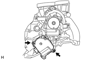
INSTALL HEATER CONTROL CABLE SUB-ASSEMBLY (for Manual Air Conditioning System)
Note
-
When working, take care not to get dirt or dust in the gear grease.
-
Do not hold gear sections while wearing cotton work gloves.
-
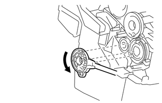
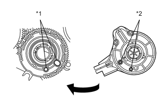
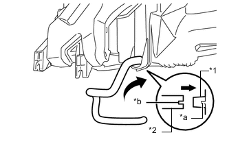
Turn the pin on the cable side as far as possible in the direction of the arrow, and position it so that it matches the hole in the gear.
Tech Tips
Set the temperature adjustment dial to MAX HOT.
-
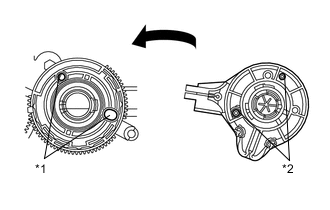
Text in Illustration *1 Drive gear hole *2 Control cable positioning pin Hold the protrusion on the drive gear, and rotate the gear until the protrusion is aligned with the cylindrical section of the case.
Tech Tips
Temperature adjustment dial: MAX HOT
-
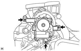
Push the control cable positioning pin in slowly until it matches the drive gear hole, and install the heater control cable sub-assembly.
-
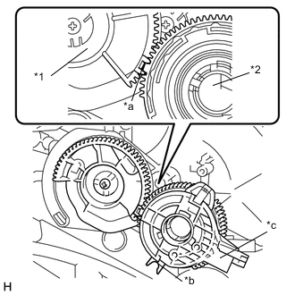
Replacing the drive gear.
-
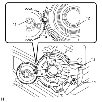
Text in Illustration *1 Shaft Gear *2 Drive Gear *a Reference Position *b Drive gear protrusion *c Cylindrical section of the case *d Resin portion of the control cable When replacing the drive gear, pull the resin portion of the control cable forward slowly and remove it.
Note
Do not pull the drive gear.
-
Pull the drive gear forward slowly and remove it.
-
Rotate the shaft gear clockwise slowly until it stops.
Note
Be sure not to turn too forcefully.
-
Match the shaft gear and the drive gear with their specified positions, and insert the drive gear slowly into the heater case.
-
-
-
INSTALL HEATER CONTROL CABLE SUB-ASSEMBLY (w/o Air Conditioning System)
Tech Tips
Use the same procedure as for the automatic air conditioning system.
-
INSTALL AIR INLET DAMPER CONTROL CABLE SUB-ASSEMBLY (for Manual Air Conditioning System)
Note
-
When working, take care not to get dirt or dust in the gear grease.
-
Do not hold gear sections while wearing cotton work gloves.
-
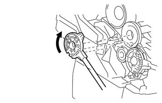
Turn the pin on the cable side as far as possible in the direction of the arrow, and position it so that it matches the hole in the gear.
Tech Tips
Set the blower dial to FACE.
-
Text in Illustration *1 Drive gear hole *2 Control cable positioning pin Hold the protrusion on the drive gear, and rotate the gear clockwise until it stops.
Tech Tips
Temperature control position: VENT
-
Push the control cable positioning pin in slowly until it matches the drive gear hole, and install the air inlet damper control cable sub-assembly.
-
Replacing the drive gear.
-
Text in Illustration *1 Mode Main Link *2 Drive Gear *a Reference Position *b Drive gear protrusion *c Resin portion of the control cable When replacing the drive gear, pull the resin portion of the control cable forward slowly and remove it.
Note
Do not pull the drive gear.
-
Pull the drive gear forward slowly and remove it.
-
Match the mode main link and the drive gear with their specified positions, and insert the drive gear slowly into the heater case.
-
-
-
INSTALL AIR INLET DAMPER CONTROL CABLE SUB-ASSEMBLY (w/o Air Conditioning System)
Tech Tips
Use the same procedure as for the automatic air conditioning system.
-
INSTALL NO. 3 AIR CONDITIONING RADIATOR DAMPER SERVO SUB-ASSEMBLY (for Automatic Air Conditioning System)
-
Align the link pin and the main link groove, and install the No. 3 air conditioner radiator damper servo sub-assembly with the three screws.
-
-
INSTALL NO. 4 AIR CONDITIONING RADIATOR DAMPER SERVO SUB-ASSEMBLY (for Automatic Air Conditioning System)
-
Install the No. 4 air conditioning radiator damper servo sub-assembly with the 2 screws.
-
-
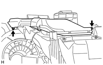
INSTALL NO. 2 AIR DUCT SUB-ASSEMBLY
-
Install the No. 2 air duct sub-assembly with the 3 screws.
-
-
INSTALL BLOWER MOTOR WITH FAN SUB-ASSEMBLY
-
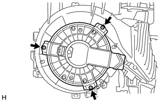
Install the blower motor with fan sub-assembly with the 3 screws.
-
-
INSTALL NO. 1 AIR DUCT SUB-ASSEMBLY
-
Install the No. 1 air duct sub-assembly with the 2 screws.
-
-
INSTALL NO. 1 COOLER UNIT DRAIN HOSE
-
Text in Illustration *1 Case *2 Hose *a Rib *b Notched section Install the No. 1 cooler unit drain hose as shown in the illustration.
Tech Tips
Align the notched section of the hose with the rib on the case.
-
-
INSTALL COVER
-
Engage the 2 claws.
-
Install the cover with the 3 screws.
-
-
INSTALL COOLER EXPANSION VALVE (for Automatic Air Conditioning System)
-
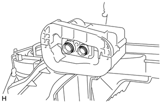
Sufficiently apply compressor oil to 2 new O-rings and the fitting surfaces. Install the 2 O-rings to the No. 1 cooler evaporator sub-assembly.
Compressor oil for HFC-134a (R134a) ND-OIL 8 or equivalent for HFO-1234yf (R1234yf) ND-OIL 12 or equivalent -
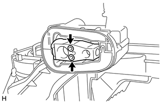
Using a 4 mm hexagon wrench, install the cooler expansion valve with packing with the 2 hexagon bolts.
- Torque:
- 3.5 N*m { 36 kgf*cm, 31 in.*lbf }
-
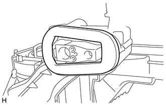
Install the new gasket.
-
-
INSTALL COOLER EXPANSION VALVE (for Manual Air Conditioning System)
Tech Tips
Use the same procedure as for the automatic air conditioning system.
-
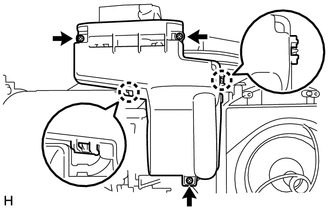
INSTALL COOLING UNIT CASE
-
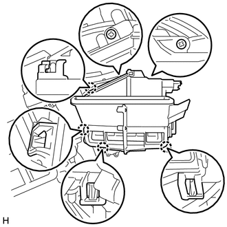
Engage the 4 claws.
-
Install the cooling unit case with the 2 screws.
-
-
INSTALL CLEAN AIR FILTER
-
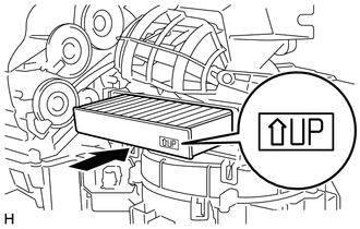
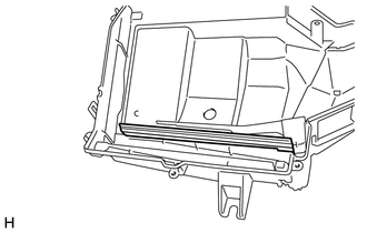
Install the clean air filter as shown in the illustration.
-
-
INSTALL AIR FILTER CASE
-
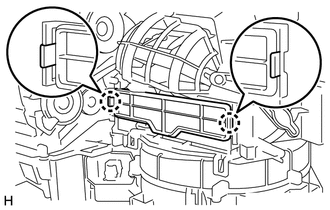
Engage the 2 claws to install the air filter case.
-
-
INSTALL HEATER RADIATOR UNIT SUB-ASSEMBLY (for Automatic Air Conditioning System)
-
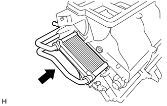
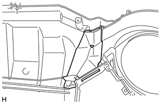
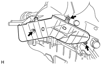
Install the heater radiator unit sub-assembly as shown in the illustration.
-
Install the clamp with the screw.
-
-
INSTALL HEATER RADIATOR UNIT SUB-ASSEMBLY (for Manual Air Conditioning System)
Tech Tips
Use the same procedure as for the automatic air conditioning system.
-
INSTALL HEATER RADIATOR UNIT SUB-ASSEMBLY (w/o Air Conditioning System)
Tech Tips
Use the same procedure as for the automatic air conditioning system.
-
INSTALL HEATER COVER (for Automatic Air Conditioning System)
-
Install the heater cover with the 3 screws.
-
-
INSTALL HEATER COVER (for Manual Air Conditioning System)
Tech Tips
Use the same procedure as for the automatic air conditioning system.
-
INSTALL HEATER COVER (w/o Air Conditioning System)
Tech Tips
Use the same procedure as for the automatic air conditioning system.
-
INSTALL NO. 5 AIR CONDITIONING RADIATOR DAMPER SERVO SUB-ASSEMBLY (for Automatic Air Conditioning System)
-
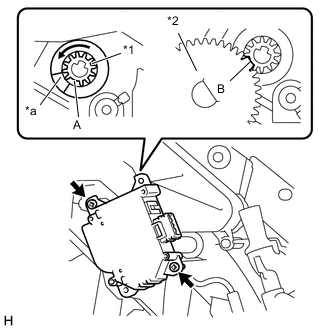
Text in Illustration *1 Air Mix Shaft *2 Drive Gear *a Reference Position Turn the air mix shaft slowly in the direction of the arrow until it stops.
Note
Be sure not to turn the air mix shaft too strongly.
-
Turn the mix shaft so that section A of the air mix shaft matches the reference position of the case.
-
Match the air mix damper server gear B section and the shaft gear A section.
-
Install the No. 5 air conditioning radiator damper servo sub-assembly with the 2 screws.
-
-
INSTALL NO. 1 AIR CONDITIONING RADIATOR DAMPER SERVO SUB-ASSEMBLY
-
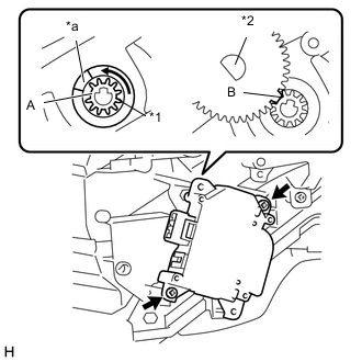
Text in Illustration *1 Air Mix Shaft *2 Drive Gear *a Reference Position Turn the air mix shaft slowly in the direction of the arrow until it stops.
Note
Be sure not to turn the air mix shaft too strongly.
-
Turn the mix shaft so that section A of the air mix shaft matches the reference position of the case.
-
Match the air mix damper server gear B section and the shaft gear A section.
-
Install the No. 1 air conditioning radiator damper servo sub-assembly with the 2 screws.
-
-
INSTALL ASPIRATOR PIPE (for Automatic Air Conditioning System)
-
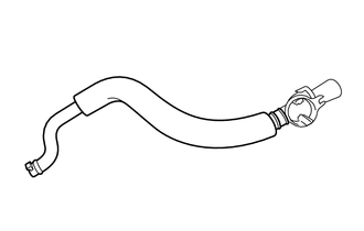
Install the aspirator pipe.
-
-
INSTALL ASPIRATOR (for Automatic Air Conditioning System)
-
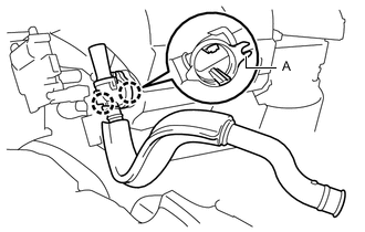
Engage the 2 claws and align the section A with the case side pin, and then install the aspirator and aspirator pipe as one unit.
-